Excitation circuit of separately excited hollow pulse generator capable of recovering residual excitation energy
A generator and pulse capacitor technology, which is applied in the directions of controlling generators, controlling generators, and controlling and protecting power generation through magnetic field changes, can solve problems such as difficult modulation of excitation current waveform, large excitation current changes, and impact of load current pulses, etc. To achieve the effect of shortening the precharge time
- Summary
- Abstract
- Description
- Claims
- Application Information
AI Technical Summary
Problems solved by technology
Method used
Image
Examples
Embodiment 1
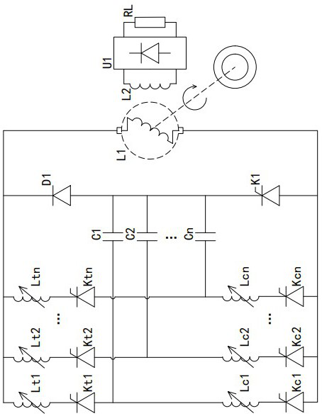
[0023] Such as figure 1 As shown, a separately excited air-core pulse generator excitation circuit that can recover residual excitation energy includes an excitation winding L1, an armature winding L2 and a prime mover. The prime mover is connected to the excitation winding to drive the excitation winding to rotate. The armature winding L2 Both ends are connected to the input end of the rectification circuit U1, and the output end of the rectification circuit U1 is connected to the load RL.
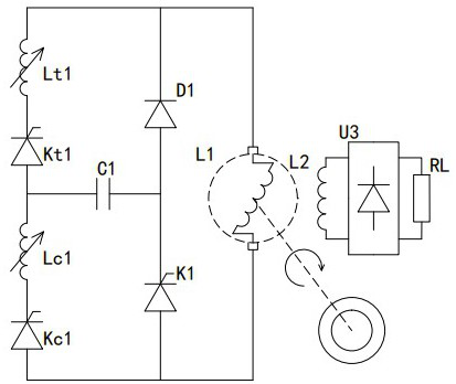
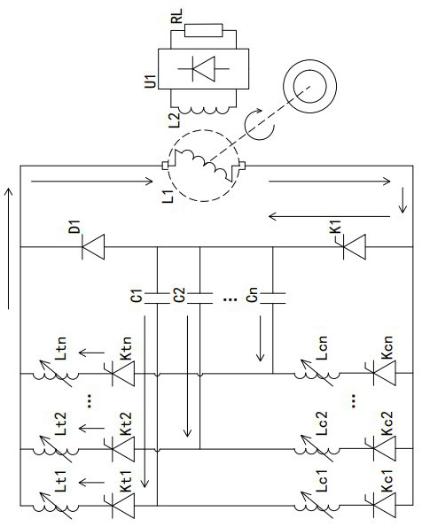
[0024] A pulse capacitor module is connected in parallel at both ends of the excitation winding L1, combined with figure 2 , the capacitor module includes excitation regulation inductor (hereinafter referred to as inductor) Lt1, excitation control switch (hereinafter referred to as switch tube) Kt1, recovery regulation inductor (hereinafter referred to as inductor) Lc1 and recovery control switch (hereinafter referred to as switch tube) Kc1, inductor Lt1 One end of the freewheeling diod...
Embodiment 2
[0037]The difference between this embodiment and Embodiment 1 is that in this embodiment, the excitation adjustment inductances Lt1˜Ltn are omitted. When the requirements for the current waveform when the pulse capacitor is discharged and the current waveform modulation during recovery are not high, the excitation adjustment inductance and the recovery adjustment inductance can be simplified into one group and set in the branch of the pulse capacitor bank to form a Image 6 The circuit configuration shown.
[0038] Such as Image 6 As shown, the cathodes of switch tube Kt1, switch tube Kt2, ... switch tube Ktn are connected to the cathode of freewheeling diode D1 and one end of excitation winding L1 at the same time, and the anodes of switch tube Kt1, switch tube Kt2, ... switch tube Ktn are respectively connected to The cathodes of switch tubes Kc1 , switch tubes Kc2 , . The anodes of the switching tube Kc1, the switching tube Kc2, ..., the switching tube Kcn are connected ...
PUM
 Abstract
Description
Claims
Application Information
 - R&D
- Intellectual Property
- Life Sciences
- Materials
- Tech Scout
- Unparalleled Data Quality
- Higher Quality Content
- 60% Fewer Hallucinations
Browse by: Latest US Patents, China's latest patents, Technical Efficacy Thesaurus, Application Domain, Technology Topic, Popular Technical Reports.
© 2025 PatSnap. All rights reserved.Legal|Privacy policy|Modern Slavery Act Transparency Statement|Sitemap|About US| Contact US: help@patsnap.com


