
A fast collection device and method for collecting and cleaning building formwork cutting waste

A technology of building templates and collection devices, applied in cleaning methods and appliances, cleaning methods using tools, cleaning methods using gas flow, etc., can solve the problems of centralized waste cleaning, dust explosion, safety hazards, etc., and reduce labor force The process of input and transmission is smooth and the effect of improving efficiency

Active Publication Date: 2022-02-25
江苏林之源木业有限公司
View PDF6 Cites 0 Cited by
  • Summary
  • Abstract
  • Description
  • Claims
  • Application Information

AI Technical Summary

Problems solved by technology

[0002] When the building formwork is cut, a certain amount of leftovers and some powdery wastes will be produced. The existing cleaning methods are mostly manual cleaning, which is inefficient, and in the process of manual cleaning, due to the flow of air, the Powdery waste floats in the air to form smoke dust, which will not only cause certain hidden dangers to the health of the staff, but also easily cause dust explosions when encountering open flames, posing certain safety hazards
[0003] Manual cleaning is still unable to realize centralized cleaning of waste materials in a certain area, especially in the large-volume construction formwork cutting area. Waste cleaning requires a lot of labor, which increases cleaning costs and cannot be achieved in a short time. The purpose of cleaning, therefore, proposes a kind of fast collection device for building formwork cutting waste that can perform batch cleaning on waste materials, reduce labor input, and realize high-speed cleaning to solve the above problems

Method used


Image

  • A fast collection device and method for collecting and cleaning building formwork cutting waste
  • A fast collection device and method for collecting and cleaning building formwork cutting waste
  • A fast collection device and method for collecting and cleaning building formwork cutting waste

Examples


Embodiment 1

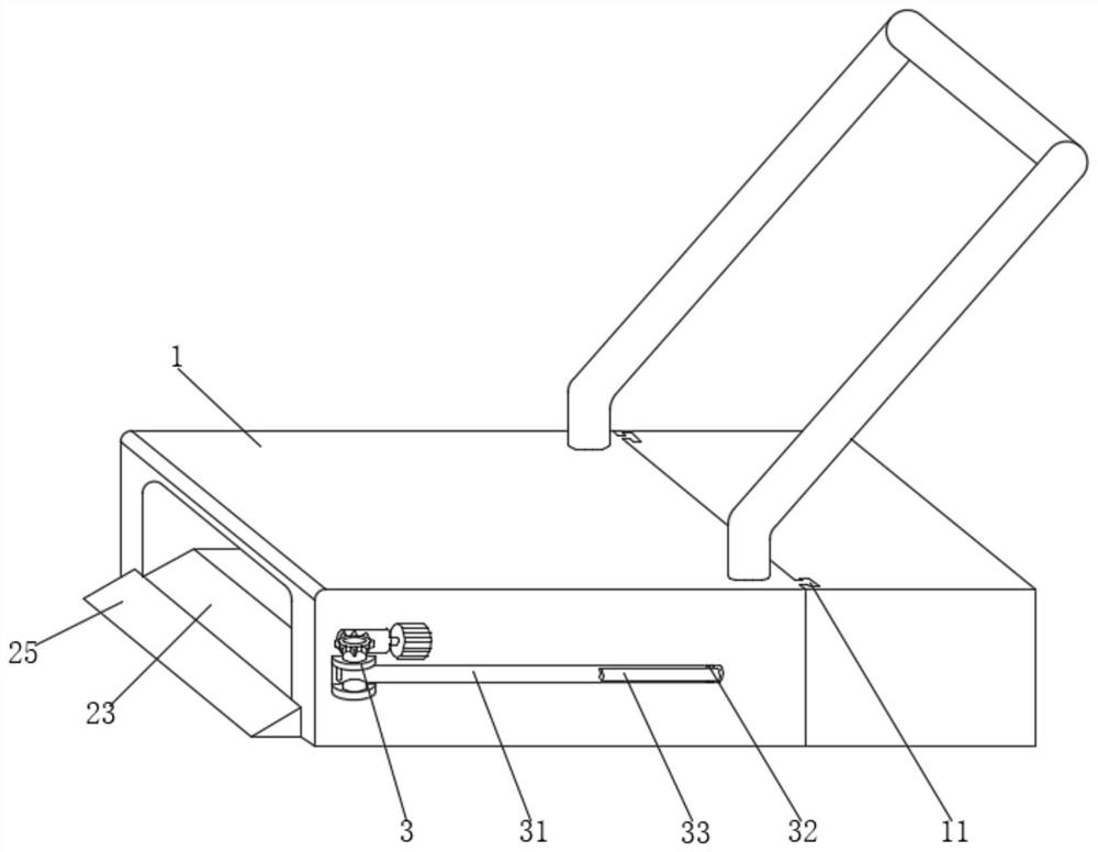
[0033] see Figure 1-5 , the present embodiment provides a device for quickly collecting building formwork cutting waste, including a collection bin 1, one end of the collection bin 1 is provided with a collection box for storing waste materials, and the bottom surfaces of the collection bin 1 and the collection box are both provided with rollers, collecting The bin 1 can move freely in the area where waste materials exist through the handle provided on its top surface, thereby making the collection and processing of waste materials more convenient.

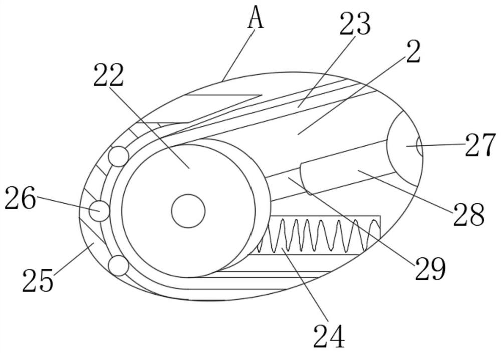
[0034] The end of the inner wall of the bottom side of the collection bin 1 close to the opening is provided with a mounting groove 2. The mounting groove 2 can enable the conveyor belt 23 to be installed in an inlaid manner, so that the non-working surface of the conveyor belt 23 does not contact the waste material, which helps the waste material in the collection bin. 1 smooth shipping inside.

[0035] The inside of the installa...

Embodiment 2

[0053] see Figure 1-3 , on the basis of embodiment 1, a further improvement has been made: the size of the waste produced during the cutting of the building formwork is different, there are large and small, and manual assistance is required for the smaller waste to be able to realize the waste to the interior of the collection bin 1 transfer.

[0054] In order to further reduce the height difference between the end of the transmission belt 23 and the ground, the inner wall of the bottom side of the installation groove 2 is inserted with a movable platform 25 through the movable groove 24, and the movable platform 25 can adjust the distance between the transmission belt 23 and the ground. Supplementary, can eliminate the impact of height difference on the process of waste contacting the conveyor belt 23 .

[0055] An extension spring is arranged between one end of the movable platform 25 extending into the inside of the movable groove 24 and the inwall of the movable groove 2...

Embodiment 3

[0063] see Figure 6-7 , On the basis of Embodiment 1, a further improvement has been made: in order to further enhance the scope of the single disturbance of the telescopic rod 31 and the deflection rod 33 to waste.

[0064] Both the fixed cylinder 34 and the movable cylinder 35 are composed of a main rod 6 and an auxiliary rod 61. The auxiliary rod 61 is plugged into the inside of the main rod 6. The change in the length between the auxiliary rod 61 and the main rod 6 can directly change the overall length of the telescopic rod 31. The change of the length, and then change the radius of the sweeping range when the telescopic rod 31 deflects once, can change the range of the waste material.

[0065] In order to make the change of the length between the main rod 6 and the auxiliary rod 61 more convenient, one end of the auxiliary rod 61 extending into the main rod 6 is provided with a deformation groove 63, and the inside of the deformation groove 63 is integrally provided wit...


PUM


Abstract

The invention discloses a fast collection device and a collection and cleaning method for building formwork cutting waste, and relates to the technical field of waste collection, including a collection bin. There is an installation slot on the inner wall of the bottom side of the collection bin near the opening, and a transmission belt is installed inside the installation slot through the power wheel and the adjustment wheel, and the motor that provides power for the power wheel is installed on the inner wall of the installation slot. The side outer wall near its opening is hinged with a telescopic rod through the telescopic ear, and the end of the telescopic rod far away from the telescopic ear is hinged with a deflection rod through the deflection ear. Gears are fixed. Through the combined use of the above devices, the cutting waste can be collected in batches, the efficiency of waste collection and cleaning can be improved, and at the same time, the labor input can be reduced, and the cost of waste collection and cleaning can be saved.

Description

technical field [0001] The invention relates to the related technical field of waste collection, in particular to a device for quickly collecting construction formwork cutting waste and a method for collecting and cleaning it. Background technique [0002] When the building formwork is cut, a certain amount of leftovers and some powdery wastes will be produced. The existing cleaning methods are mostly manual cleaning, which is inefficient, and in the process of manual cleaning, due to the flow of air, the The powdery waste floats in the air and forms smoke, which not only poses certain hidden dangers to the health of the staff, but also is prone to dust explosions when exposed to open flames, posing certain safety hazards. [0003] Manual cleaning is still unable to realize centralized cleaning of waste materials in a certain area, especially in the large-volume construction formwork cutting area. Waste cleaning requires a lot of labor, which increases cleaning costs and can...

Claims


Application Information

Patent Timeline
Patent Type & Authority Patents(China)
IPC IPC(8): B08B1/00B08B5/04B08B13/00
CPCB08B1/00B08B5/04B08B13/00
Inventor 梁永前
Owner 江苏林之源木业有限公司
Learn More