Building steel bar cutting device

A cutting device, a technology for building steel bars, applied in the directions of transportation and packaging, stacking of objects, etc., can solve problems such as affecting the normal use of steel bars, bending and deformation of steel bars, easy swinging and cluttering, etc.

Inactive Publication Date: 2021-03-12
钟玲
View PDF0 Cites 4 Cited by
  • Summary
  • Abstract
  • Description
  • Claims
  • Application Information

AI Technical Summary

Problems solved by technology

After the existing steel bar cutting device cuts the steel bar, the steel bar often falls to the ground by its own weight. During the falling process, the steel bar is easily bent and deformed, which affec

Method used


Image

  • Building steel bar cutting device
  • Building steel bar cutting device
  • Building steel bar cutting device

Examples


Embodiment 1

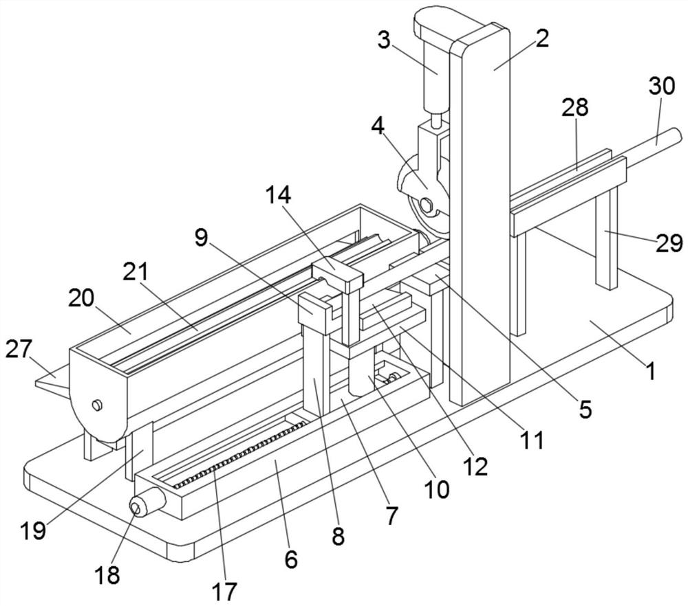
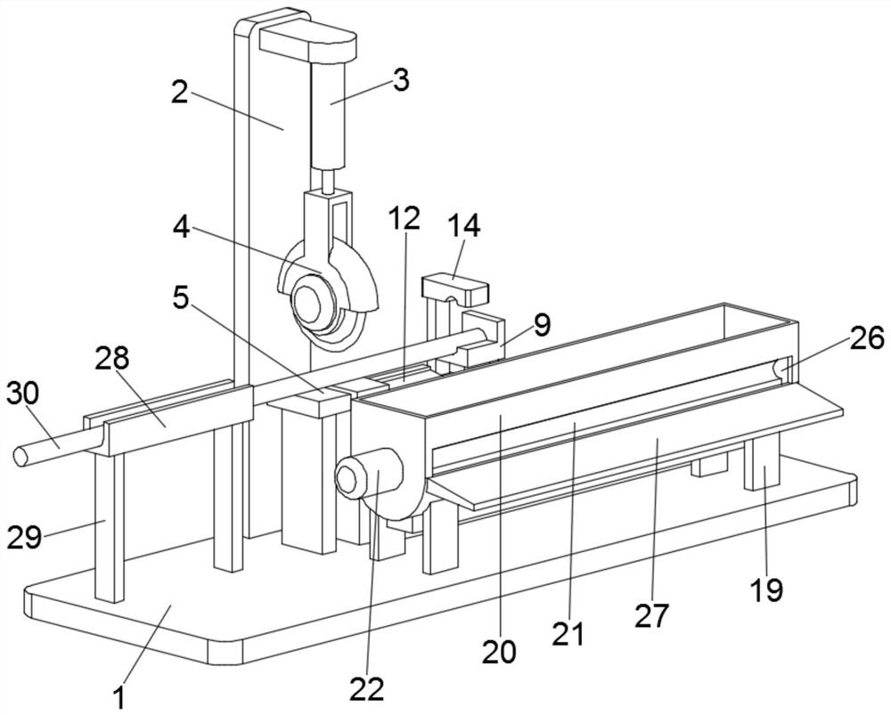
[0026] see Figure 1-2 , a construction reinforcement cutting device, comprising a base 1, a first support frame 2, a cutting machine 4 and a cutting table 5, the first support frame 2 and the cutting table 5 are fixedly installed on the base 1, the first support The top of the frame 2 is provided with a first driving cylinder 3, the lower end of the first driving cylinder 3 is equipped with a cutting machine 4, and the cutting machine 4 is located directly above the cutting table 5;

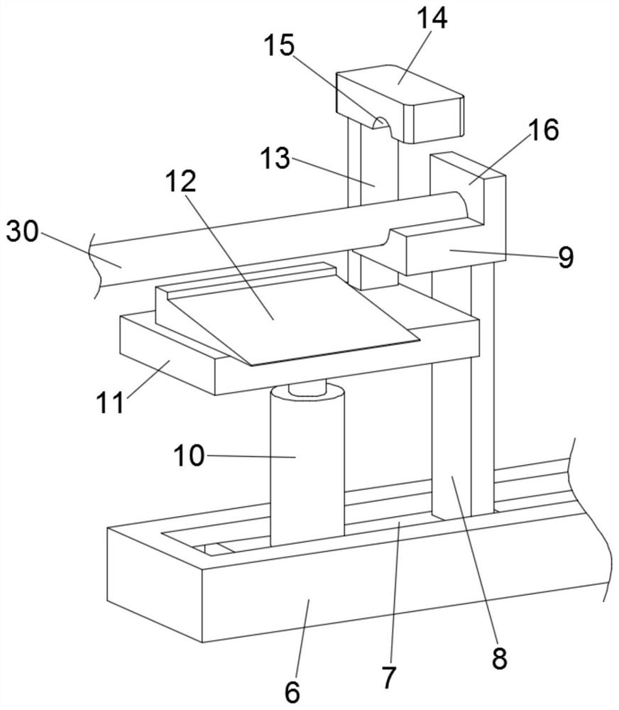
[0027] see image 3 , one side of the cutting table 5 is provided with a reinforcing bar fixing mechanism, and the reinforcing bar fixing mechanism includes a slide rail 6, a supporting plate 9, a second drive cylinder 10 and a pressing plate 14, and the slide rail 6 is fixedly installed on the base 1, and the A slide plate 7 is slidably embedded in the slide rail 6, and a translation assembly for driving the slide plate 7 to move horizontally is arranged in the slide rail 6, and a second suppo...

Embodiment 2

[0038] A construction reinforcement cutting device, comprising a base 1, a first support frame 2, a cutting machine 4 and a cutting table 5, the first support frame 2 and the cutting table 5 are fixedly installed on the base 1, the first support frame 2. A first driving cylinder 3 is provided on the top, and a cutting machine 4 is installed at the lower end of the first driving cylinder 3, and the cutting machine 4 is located directly above the cutting table 5;

[0039] One side of the cutting table 5 is provided with a reinforcing bar fixing mechanism, and the reinforcing bar fixing mechanism includes a slide rail 6, a supporting plate 9, a second drive cylinder 10 and a pressing plate 14, and the slide rail 6 is fixedly installed on the base 1, and the A slide plate 7 is slidably embedded in the slide rail 6, and a translation assembly for driving the slide plate 7 to move horizontally is provided in the slide rail 6, and a second support frame 8 and a second drive cylinder 1...


PUM


Abstract

The invention discloses a building steel bar cutting device which comprises a base, a first supporting frame, a cutting machine and a cutting table. A steel bar fixing mechanism is arranged on one side of the cutting table. The building steel bar cutting device further comprises a transfer mechanism. According to the building steel bar cutting device, the liftable steel bar fixing mechanism is arranged on one side of the cutting table, and the distance between a supporting plate and the cutting table can be adjusted according to different requirements, so that cutting operation of steel bars with different lengths is achieved; and after cutting is finished, a second driving cylinder stretches out to drive a pressing plate to ascend and make contact with the steel bars to clamp and fix thesteel bars, meanwhile, an inclined plate synchronously ascends to lift the steel bars, then the steel bars roll into grooves of a rotary barrel of a transfer box along the inclined plate, and when thesteel bars rotate along with the rotary barrel and rotate to the bottom of the transfer box, an air blower blows air to radiate heat and cool the steel bars quickly, and then the steel bars are discharged from a discharge opening, so that batch collection of the steel bars is achieved, the process is coherent, manual intervention is not needed, and the machining efficiency is high.

Description

technical field [0001] The invention relates to the technical field of building construction, in particular to a building steel bar cutting device. Background technique [0002] In the process of building construction, it is often necessary to cut off the steel bars so that the steel bars can meet the use requirements in the construction process. After the existing steel bar cutting device cuts the steel bar, the steel bar often falls to the ground by its own weight. During the falling process, the steel bar is easily bent and deformed, which affects the normal use of the steel bar. In addition, in order to collect the steel bar uniformly, it usually needs to be manually Putting the cut steel bars together is labor-intensive and easy to swing messily. Contents of the invention [0003] The object of the present invention is to provide a construction steel bar cutting device to solve the problems raised in the above-mentioned background technology. [0004] To achieve the...

Claims


Application Information

Patent Timeline
IPC IPC(8): B21F11/00B65G57/18
CPCB21F11/00B65G57/18
Inventor 钟玲
Owner 钟玲
Why Eureka
Try Eureka