Automatic separating and discharging device for double-fork forgings

An automatic separation and unloading device technology, applied in the direction of stripping device, feeding device, positioning device, etc., can solve the problems of cumbersome operation, high punching efficiency, easy to scratch, etc., to ensure the separation effect and the sliding effect , to ensure the effect of rhythm

Active Publication Date: 2021-09-24
山东豪迈精锻科技有限公司
View PDF6 Cites 1 Cited by
  • Summary
  • Abstract
  • Description
  • Claims
  • Application Information

AI Technical Summary

Problems solved by technology

[0002] The double-fork forgings (such as Figure 4 As shown) the specific structure is that there are flash edges 103 around, and a symmetrical double fork 101 is arranged at both ends, and there is a connecting skin 102 between the double fork 101. After the press completes punching of the double fork forging, the flying The edge, the skin and the double fork are often still inlaid together. The traditional way is to separate the three by light knocking. Separation also needs to be classified. At present, most of them are manually operated. Due to the high efficiency of punching and the low efficiency of manual separation and classification, it has been unable to meet the actual production needs.

Method used


Image

  • Automatic separating and discharging device for double-fork forgings
  • Automatic separating and discharging device for double-fork forgings
  • Automatic separating and discharging device for double-fork forgings

Examples


Embodiment Construction

[0033] In order to facilitate the understanding of those skilled in the art, the present invention will be further described below in conjunction with the accompanying drawings.

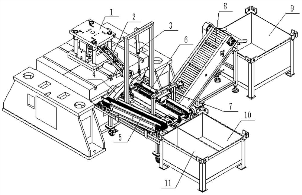
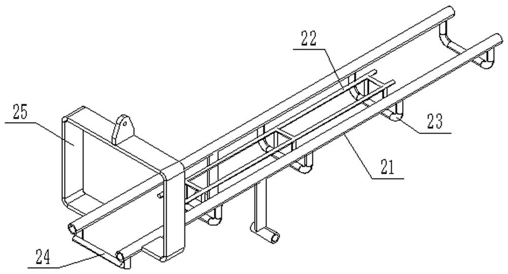
[0034] Such as Figure 1 to Figure 3 As shown, a double-fork automatic separation and unloading device for forgings is arranged on one side of the press 1, and specifically includes a skin-to-skin separation conveying slide 2, which slopes downward along the conveying direction, and the skin-to-skin separation The conveying chute 2 includes two slide bars 21, the bottoms of the two slide bars 21 are connected by a bottom connecting rod 23, the distance between the two slide bars 21 is greater than the distance between the outermost sides of the double forks 101 and less than the width of the flash 102, and the bottom of the two slide bars 21 is connected The distance between the rod 23 and the slide bar 21 is greater than the length of the double fork 101 at one end of the double fork forging. The pr...


PUM


Abstract

The invention discloses an automatic separating and discharging device for double-fork forgings, and belongs to the field of punching, separating and conveying. The device comprises a recess separating and conveying slide way, the recess separating and conveying slide way is inclined downwards, a stop lever is arranged below the tail end of the recess separating and conveying slide way, and when the double-fork forgings slide downwards, double forgings at the bottom are in contact with the stop lever to turn over the double-fork forgings; a flash separating and conveying line is arranged at the bottom of the tail end of the recess separating and conveying slide way, the recess separating and conveying line comprises two parallel flash conveying chains, a pressing device is arranged above the two flash conveying chains, the double forks of the double-fork forgings on the flash conveying chains can be pressed down by the pressing device, and a double-fork conveying line is arranged at the bottom of the middle of the two parallel flash conveying chains; and the device further comprises a recess conveying chain, the recess conveying chain is arranged on one side of the flash separating and conveying line, a wad collecting inclined sliding way is arranged at the bottom of the recess separating and conveying sliding way, the recess conveying chain is arranged at the tail end of the wad collecting inclined sliding way, and separation and collection of flashes, recesses and the double forks can be achieved through the structure.

Description

technical field [0001] The invention relates to the field of punching, cutting, separating and conveying, in particular to an automatic separating and unloading device for double forked forgings. Background technique [0002] The double-fork forgings (such as Figure 4 As shown) the specific structure is that there are flash edges 103 around, and a symmetrical double fork 101 is arranged at both ends, and there is a connecting skin 102 between the double fork 101. After the press completes punching of the double fork forging, the flying The edge, the skin and the double fork are often still inlaid together. The traditional way is to separate the three by light knocking. Separation also needs to be classified. At present, most of them are manually operated. Due to the high efficiency of punching and the low efficiency of manual separation and classification, it has been unable to meet the actual production needs. [0003] In view of the above-mentioned problems in the prior ...

Claims


Application Information

Patent Timeline
Patent Type & Authority Applications(China)
IPC IPC(8): B21D43/12B21D43/18B21D45/06B07B13/05B07B13/16
CPCB21D43/12B21D43/18B21D45/06B07B13/05B07B13/16
Inventor 于同庆田敬林高强强邱宪路
Owner 山东豪迈精锻科技有限公司
Why Eureka
Try Eureka