Welding flux barrel for electroslag pressure welding for building

A construction electricity and pressure welding technology, which is applied in the field of construction electric welding, can solve the problems of misalignment of steel bars, unqualified engineering, and easy dripping of welding packages, so as to achieve the effect of convenient disassembly and prevention of deviation

Pending Publication Date: 2021-09-24
山东逸晨机械设备有限公司
View PDF7 Cites 0 Cited by
  • Summary
  • Abstract
  • Description
  • Claims
  • Application Information

AI Technical Summary

Problems solved by technology

[0002] Electroslag pressure welding is to place two steel bars in a vertical or oblique (inclination range of 4:1) butt joint form, using welding current to pass through the gap between the two steel bars, forming an arc process and an electroslag process under the flux layer, resulting in Arc heat and resistance heat, melting steel bars, pressurized to complete a pressure welding method, electroslag pressure welding is often used to load flux in the flux barrel, the current electroslag pressure welding often has the problem that the two steel bars are not in the same axis, easy to bend Folding, the welding package is easy to drip down, resulting in unqualified project

Method used


Image

  • Welding flux barrel for electroslag pressure welding for building
  • Welding flux barrel for electroslag pressure welding for building
  • Welding flux barrel for electroslag pressure welding for building

Examples


Embodiment Construction

[0030] The following are specific embodiments of the present invention and in conjunction with the accompanying drawings, the technical solutions of the present invention are further described, but the present invention is not limited to these embodiments.

[0031]In the description of the present invention, it should be noted that the orientation or positional relationship indicated by the terms "inner", "lower", etc. is based on the orientation or positional relationship shown in the drawings, or the conventionally placed position when the product of the invention is used. Orientation or positional relationship is only for the convenience of describing the present invention and simplifying the description, and does not indicate or imply that the referred device or element must have a specific orientation, be constructed and operated in a specific orientation, and thus should not be construed as a limitation of the present invention. In addition, the terms "first", "second", e...


PUM


Abstract

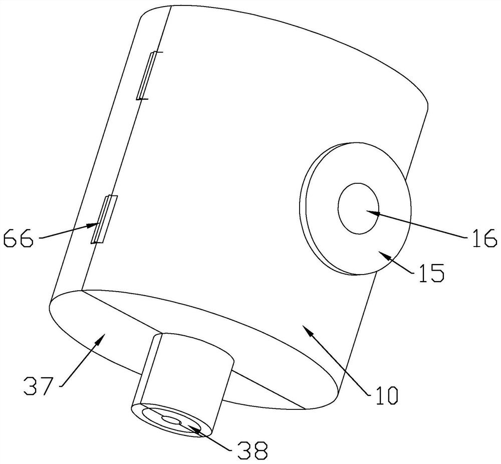
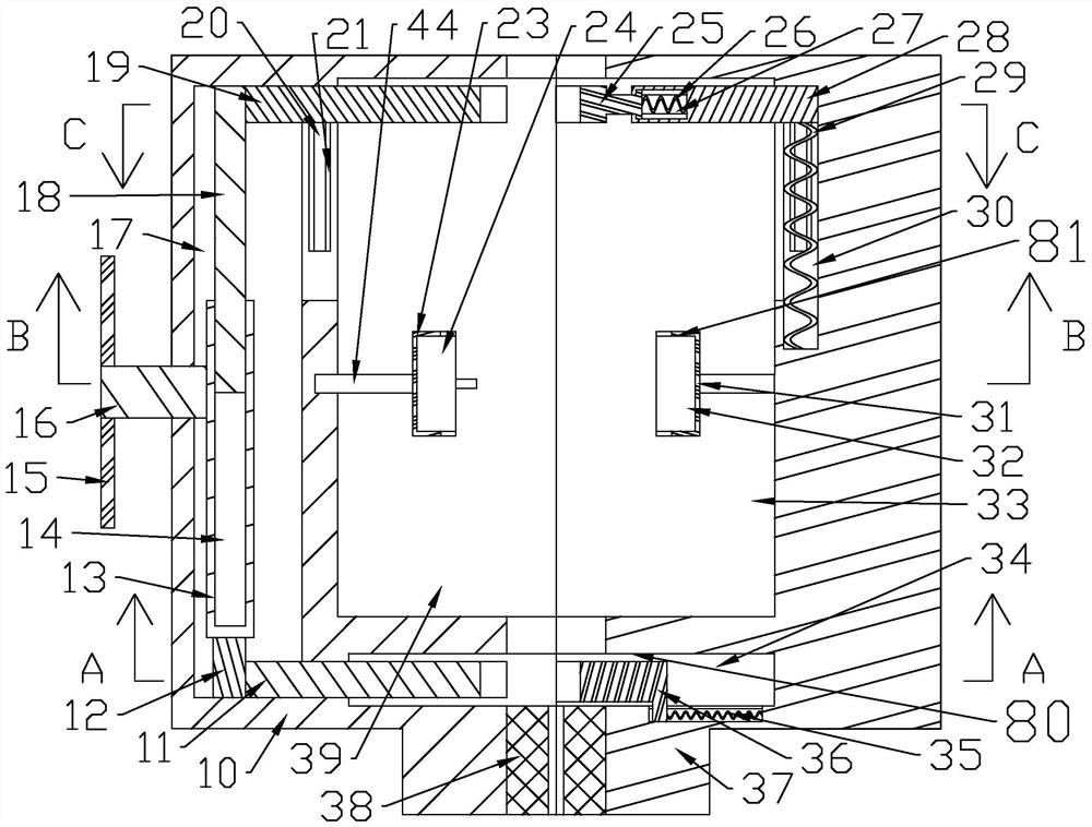
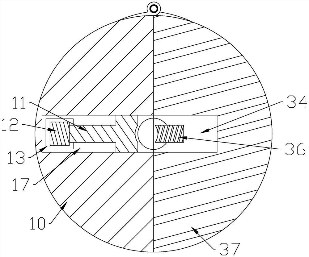
The invention belongs to the field of building electric welding, and particularly relates to a welding flux barrel for electroslag pressure welding for building. The welding flux barrel comprises a first welding flux barrel wall and a second welding flux barrel, the first welding flux barrel wall and the second welding flux barrel are connected together, bulges are arranged on the same side of the first welding flux barrel wall and the second welding flux barrel, sealing sponges are fixedly arranged in the bulges, a second half reaction space with an opening facing the second welding flux barrel is formed in the first welding flux barrel wall, a first half reaction space with an opening facing the first welding flux barrel wall is formed in the second welding flux barrel, a concentric mechanism is arranged in the first welding flux barrel wall, the inner wall of the second half reaction space and the inner wall of the first half reaction space are respectively provided with a welding bag downward-flowing preventing mechanism controlled by the concentric mechanism, and the welding bag downward-flowing preventing mechanism is internally provided with a fixed self-locking mechanism which enables the welding bag downward-flowing preventing mechanism to be closed. Through the welding flux barrel, welding bags can be effectively prevented from flowing down, and the problem of reinforcing steel bar bending and reinforcing steel bar coaxiality is solved.

Description

technical field [0001] The invention belongs to the field of building electric welding, in particular to a flux barrel for building electroslag pressure welding. Background technique [0002] Electroslag pressure welding is to place two steel bars in a vertical or oblique (inclination range of 4:1) butt joint form, using welding current to pass through the gap between the two steel bars, forming an arc process and an electroslag process under the flux layer, resulting in Arc heat and resistance heat, melting steel bars, pressurized to complete a pressure welding method, electroslag pressure welding is often used to fill the flux tank with flux, the current electroslag pressure welding often has problems that the two steel bars are not in the same axis, easy to bend Folding, the welding package is easy to drip down, resulting in unqualified project. Contents of the invention [0003] The object of the present invention is to solve the above-mentioned problems in the prior ...

Claims


Application Information

Patent Timeline
Patent Type & Authority Applications(China)
IPC IPC(8): B23K25/00
CPCB23K25/00
Inventor 龚婷婷
Owner 山东逸晨机械设备有限公司
Why Eureka
Try Eureka