Laser galvanometer scanning system

A laser vibrating mirror and scanning system technology, applied in optics, optical components, instruments, etc., can solve problems such as corrosion of electronic components, easy adhesion of field mirror surface by external dust, increased technical cost, etc., to reduce processing time and improve processing Efficiency, the effect of reducing technology costs

Active Publication Date: 2021-09-24
深圳市力智鉴实业有限公司
View PDF18 Cites 2 Cited by
  • Summary
  • Abstract
  • Description
  • Claims
  • Application Information

AI Technical Summary

Problems solved by technology

[0005] In order to solve the above-mentioned technical problems, the present invention provides a laser galvanometer scanning system to solve the problem that the existing laser galvanometer uses a single beam galvanometer for scanning during the scanning process, which makes the efficiency of laser scanning low, thereby increasing the technical cost, and when the existing laser vibrating mirror is not in use, due to the lack of an effective protective structure outside the field mirror, the surface of the field mirror is easily attached by external dust, thereby affecting the use of the field mirror, and the existing laser vibrating mirror is in a humid environment When working under the environment, humid air will enter the oscillating mirror housing along the cooling holes, so that the electronic components inside the galvanizing housing are prone to corrosion, which greatly reduces the service life of the laser oscillating mirror.

Method used


Image

  • Laser galvanometer scanning system
  • Laser galvanometer scanning system
  • Laser galvanometer scanning system

Examples


Embodiment

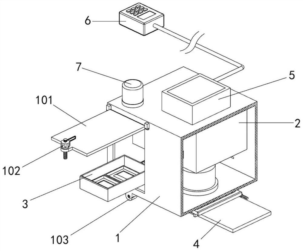
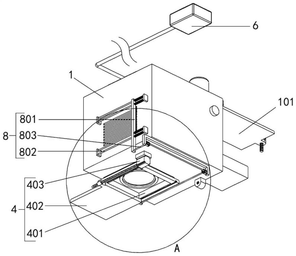
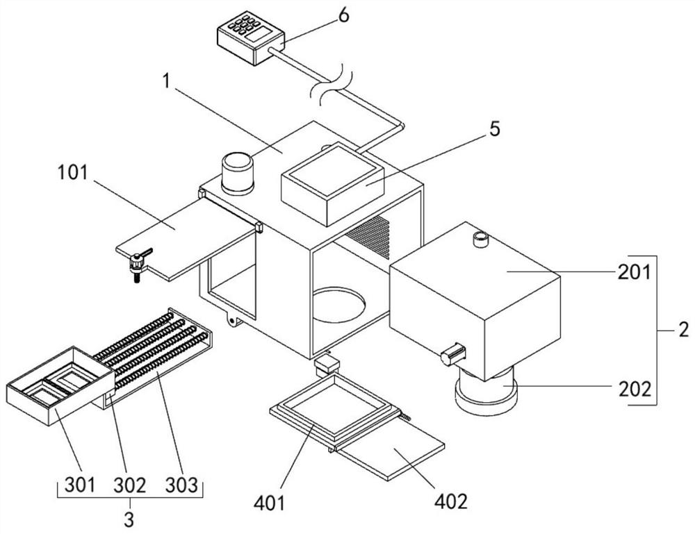
[0035] Append figure 1 Adherent Figure 8 Down:

[0036] The present invention provides a laser spray mirror scanning system, including: housing 1; inner portion of the housing 1 is provided with a spray mirror support mechanism 2, and the upper left end of the inner front side of the housing 1 is opened; the housing 1 includes a sealing plate 101 , The hand-tissue bolt 102, the connection nut 103 and the temperature and humidity sensor 104, the front end surface inspection opening of the housing 1 is rotated by the rotating shaft 101, and the lower end of the sealing plate 101 slides through the hand-rolled bolt 102; the connection nut 103 is fixed The front side of the upper end surface of the housing 1, and the connection nut 103 is threaded with the hand-rolled bolt 102 stud, the upper left side of the housing 1 is attached to the upper left side surface of the housing 1, and the temperature and humidity sensor 104 is mounted, and the temperature and humidity sensor 104 passes ...


PUM


Abstract

The invention provides a laser galvanometer scanning system, belongs to the technical field of laser galvanometers, and aims at solving problems that in the scanning process of an existing laser galvanometer, due to the fact that a single light beam galvanometer is adopted for scanning, laser scanning efficiency is low, and then technical cost is increased. The system comprises a shell, wherein a galvanometer supporting mechanism is arranged in the shell, and an inspection opening is formed in a left end of the front side in the shell; a drying piece is arranged in the shell and located at the inspection opening, a through hole is formed in the right side of the bottom end face of the shell, and a protection piece is arranged on a bottom end face of the shell and located outside the through hole; a control box is installed on a top end face of the shell and connected with a control switch through a wire, and an audible and visual alarm is installed at a left included angle of the front side of the top end face of the shell. The multi-beam galvanometer scanning system is adopted for scanning, laser scanning efficiency is greatly improved, then the technical cost is reduced, machining efficiency is improved, and the machining time is shortened.

Description

Technical field [0001] The present invention belongs to the field of laser gasel, and more particularly to a laser spray mirror scanning system. Background technique [0002] The laser spray mirror is also called a laser scanner, composed of an X-Y optical scanner, an electronic drive amplifier, and an optical reflective lens. The signal supplied by the computer controller drives the optical scan head by driving the amplifying circuit, thereby controlling the deflection of the laser beam at the X-Y plane. Simple mirror is simple to use a scanning spray in the laser industry. The so-called galvanometer, it can also be called a current meter, and its design idea is completely designed with the current table, the lens replaces the table needle, and the signal of the probe is replaced by the computer-5V-5V or -10V- + 10V DC signal. To complete the predetermined action. [0003] For example, application number: CN201510824554.8 The present invention discloses a vibrating mirror-type l...

Claims


Application Information

Patent Timeline
Patent Type & Authority Applications(China)
IPC IPC(8): G02B26/10G02B26/08G02B27/00B01D53/26
CPCG02B26/101G02B26/0875G02B27/0006B01D53/26
Inventor 杨国辉初冬梅路钧杰
Owner 深圳市力智鉴实业有限公司
Why Eureka
Try Eureka