
Bandwidth allocation method, device and equipment

A bandwidth allocation method and bandwidth technology, applied in the field of network communication, can solve problems such as unreasonable use, difficulty in avoiding network packet loss, and inability to use network bandwidth reasonably and effectively, so as to improve bandwidth utilization and improve rationality. Effect

Active Publication Date: 2021-09-24
NEW H3C TECH CO LTD
View PDF7 Cites 0 Cited by
  • Summary
  • Abstract
  • Description
  • Claims
  • Application Information

AI Technical Summary

Problems solved by technology

[0003] Existing network equipment using FlexE technology can flexibly create and adjust service ports according to different needs of users. Although it breaks through the hardware limitations of ports in traditional networks, it can be used in the case of frequent network bursts and large differences in demand for different services. , it is difficult to avoid the problem of network packet loss, and the network bandwidth cannot be used reasonably and effectively
For example, one situation is: at a certain moment, the demand of users of service 1 and service 2 is very large, causing the traffic of service 1 and service 2 to exceed the configured bandwidth, resulting in packet loss. The other situation is: in addition to service 1, Except for service 2, the demand for other services is very low, and the bandwidth is basically not used. As a result, the total bandwidth usage rate corresponding to the FlexE Group is very low, and the usage is not reasonable enough.

Method used


Image

  • Bandwidth allocation method, device and equipment
  • Bandwidth allocation method, device and equipment
  • Bandwidth allocation method, device and equipment

Examples


Embodiment Construction

[0021] In order to make the objectives, technical solutions and advantages of the present invention clearer, the present invention will be described in detail below with reference to the accompanying drawings and specific embodiments.

[0022] The following is provided for this application figure 1 The process shown is described:

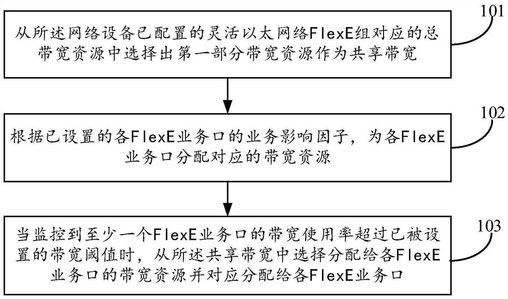
[0023] see figure 1 , figure 1 A flow chart of a bandwidth allocation method provided in the present application. This process is applied to network devices such as figure 1 As shown, the process may include the following steps:

[0024] Step 101: Select a first part of bandwidth resources as the shared bandwidth from the total bandwidth resources corresponding to the flexible Ethernet FlexE group configured by the network device.

[0025] The shared bandwidth is initially reserved; the FlexE group is bound to at least one FlexE service port.

[0026] A network device includes multiple physical ports. Multiple physical ports can use some physi...


PUM


Abstract

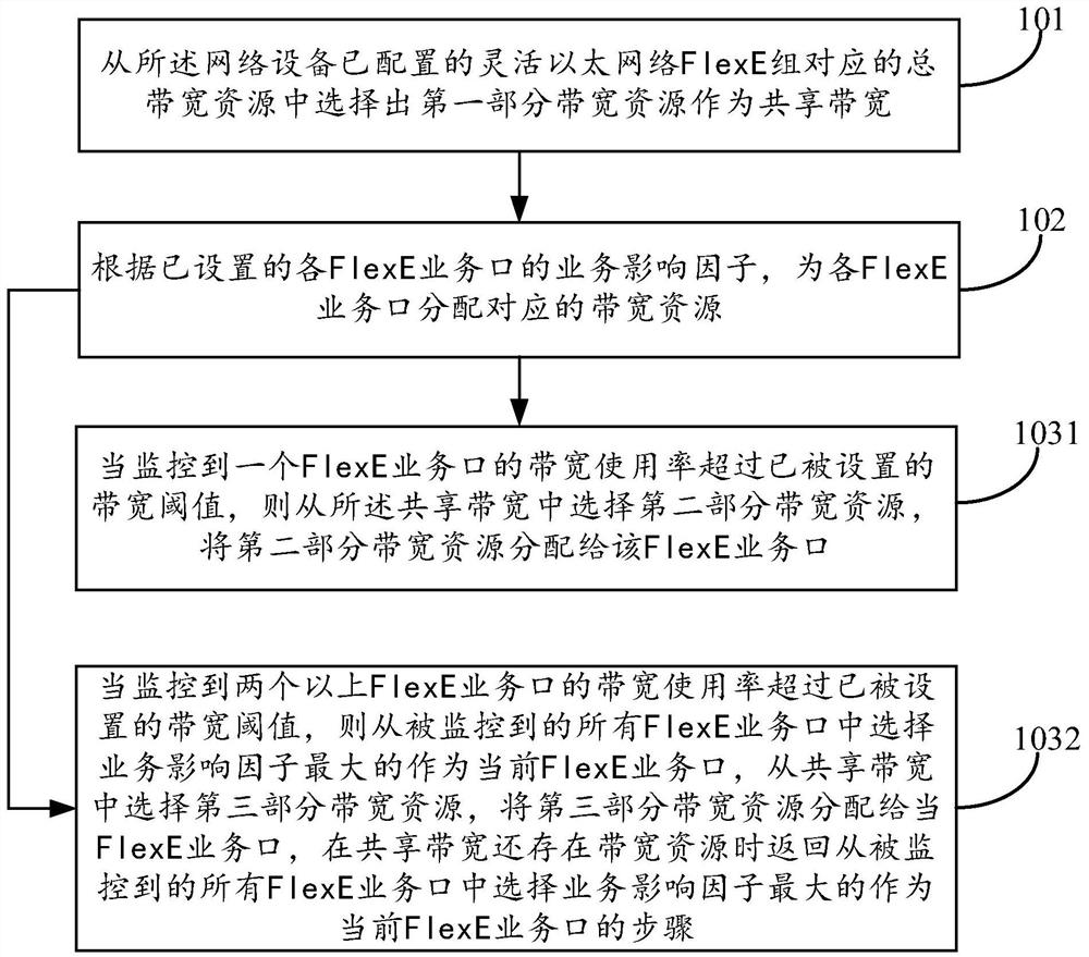
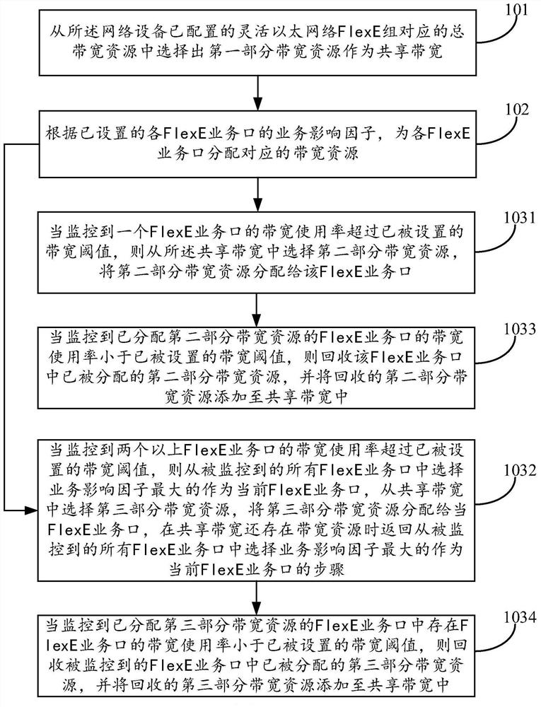
The invention provides a bandwidth allocation method, device and equipment. The network equipment selects a first part of bandwidth resources from total bandwidth resources corresponding to a configured FlexE group of the network equipment as shared bandwidth, allocates corresponding bandwidth resources to each FlexE service port, and sends the shared bandwidth to the FlexE service port when monitoring that the bandwidth utilization rate of at least one FlexE service port exceeds a set bandwidth threshold value. And selecting bandwidth resources allocated to each FlexE service port from the pre-reserved shared bandwidth, and correspondingly allocating the bandwidth resources to each FlexE service port. According to the embodiment of the invention, each FlexE service port is not limited by configured bandwidth resources any more, so that when the bandwidth utilization rate of the FlexE service port exceeds the set bandwidth threshold value, the reserved shared bandwidth is dynamically called to relieve the packet loss problem caused by service flow congestion. Meanwhile, the bandwidth utilization rate of the total bandwidth corresponding to the FlexE Group can be improved, and the rationality of bandwidth allocation can be improved.

Description

technical field [0001] The present application relates to network communication technologies, and in particular, to a bandwidth allocation method, apparatus, and device. Background technique [0002] FlexE (Flexible Ethernet, flexible Ethernet network) technology is a new flexible Ethernet technology that has recently emerged. Through the FlexE Shim layer introduced on the basis of IEEE802.3, the MAC layer (Media Access Control, medium access control layer) and PHY layer are realized. (Physical Layer, physical layer) decoupling, thereby realizing flexible rate matching. FlexE is defined based on the client / group architecture of the client. The setting of the FlexE Client can support the mapping and transmission of any number of different service ports on any PHY of the FlexE Group, so as to realize functions such as bundling, channelization and sub-rate. [0003] Existing network equipment using FlexE technology can flexibly create and adjust service ports according to diff...

Claims


Application Information

Patent Timeline
IPC IPC(8): H04L12/911H04L12/24
CPCH04L47/72H04L47/822H04L41/0896
Inventor 鲍忠明
Owner NEW H3C TECH CO LTD
Learn More