Methods and systems for in vivo full-field interference microscopy imaging

An imaging system and full-field technology, applied in the fields of eye testing equipment, medical science, diagnosis, etc., can solve the problems of predetermined phase offset, FFOCT signal degradation, and inability to construct 3D images, etc.

Pending Publication Date: 2021-09-24
巴黎科学与文学基金会 +2
View PDF1 Cites 0 Cited by
  • Summary
  • Abstract
  • Description
  • Claims
  • Application Information

AI Technical Summary

Problems solved by technology

[0009] However, current FFOCT 3D imaging schemes are feasible for static samples (or for in vivo samples with no or low motion transients), since any movement of the sample may shift the intended phase and degrade the FFOCT signal, or even destroy the FFOCT image
T...

Method used


Image

  • Methods and systems for in vivo full-field interference microscopy imaging
  • Methods and systems for in vivo full-field interference microscopy imaging
  • Methods and systems for in vivo full-field interference microscopy imaging

Examples


Embodiment Construction

[0067] system

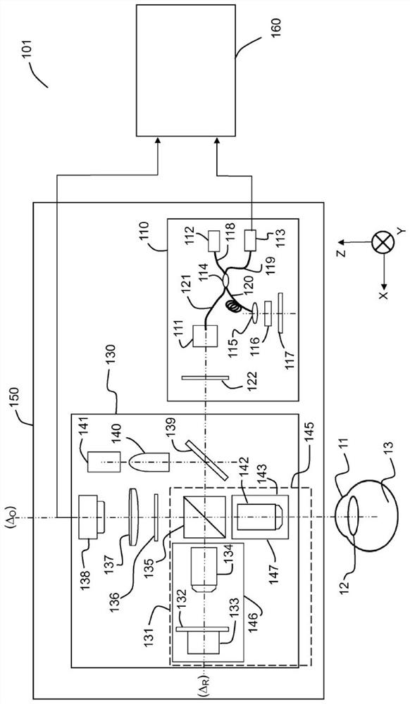
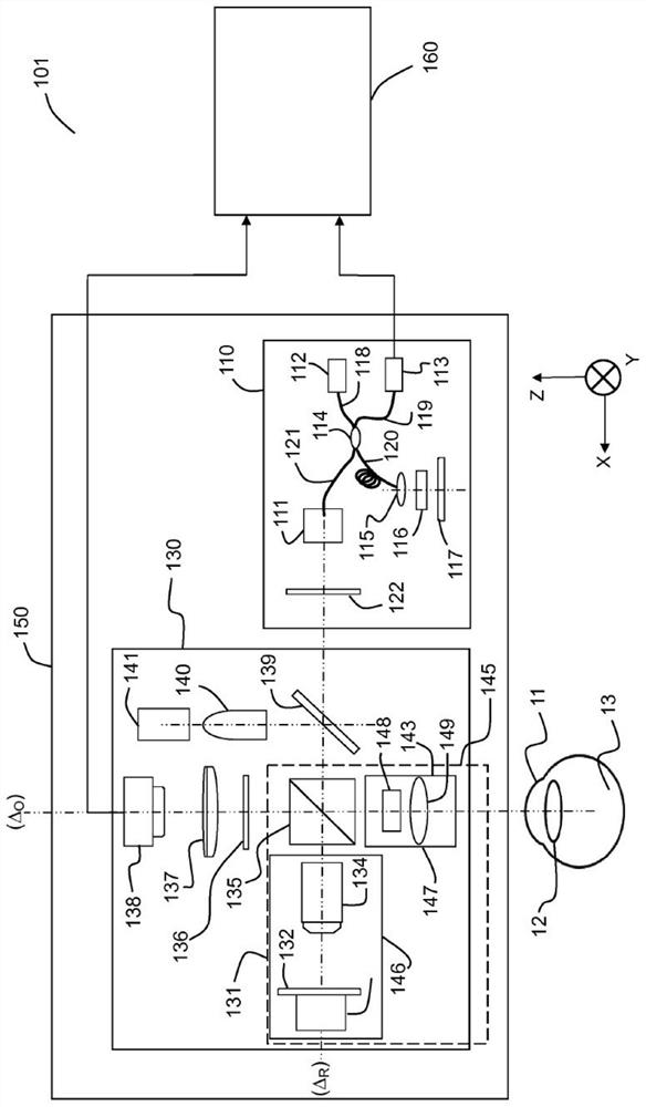
[0068] Figure 1A and Figure 1B Two embodiments 101 , 102 of systems for in vivo full-field interferometric microscopy imaging according to the present specification are shown respectively. The system 101 is suitable for implementing a method for 3D imaging of a moving sample in vivo, especially (but not limited to) the anterior portion 11 (cornea) of the eye in vivo. The system 102 is suitable for implementing a method for 3D imaging of a moving sample in vivo, especially (but not limited to) the posterior portion 13 (retina) of the eye in vivo.

[0069] Figure 1A The illustrated system 101 includes two imaging systems, a full-field OCT (“FFOCT”) imaging system 130 and an optical coherence tomography (“OCT”) imaging system 110 , and at least one processing unit 160 . An FFOCT imaging system is capable of acquiring a "frontal" image of a moving in vivo sample 11, i.e. an image of a deep section of the sample, and an optical coherence tomography ("OCT") im...


PUM


Abstract

According to one aspect, the invention relates to a system (101) for in vivo, full-field interference microscopy imaging of a scattering three-dimensional sample. It comprises a full-field OCT imaging system (130) for providing en face images of the sample, wherein said full-field OCT system comprises an interference device (145) with an object arm (147) intended to receive the sample and a reference arm (146) comprising an optical lens (134) and a first reflection surface (133), and an acquisition device (138) configured to acquire a temporal succession of two-dimensional interferometric signals (I1, I2) resulting from interferences produced at each point of an imaging field; an OCT imaging system (110) for providing at the same times of acquisition of said two-dimensional interferometric signals, cross-sectional images of both the sample and a first reflection surface (133) of said full-field OCT imaging system (130); a processing unit (160) configured to determine a plurality of en face images (X - Y) of a plurality of slices of the sample, each en face image being determined from at least two two-dimensional interferometric signals (I1, I2) having a given phase shift; determine from the cross-sectional images provided by the OCT imaging system (110) at the times of acquisition of each of said two two-dimensional interferometric signals (I1, I2) a depth (z) for each en face image (X - Y) of said plurality of slices; determine a 3D image of the sample from said plurality of en face images of said plurality of slices of the sample and depths.

Description

technical field [0001] The present specification relates to methods and systems for in vivo full-field interferometric microscopy imaging. This description applies to in vivo imaging of objects that can move randomly, and in particular relates to in vivo imaging of ocular tissues. Background technique [0002] Optical coherence tomography (OCT) has evolved over the past 25 years to become a powerful imaging modality (see, for example, “Optical Coherence Tomography-Technology and Applications”–Wolfgang Drexler–James G. Fujimoto–Editors–Springer 2015). OCT is an interferometric technique that can be thought of as an "optical analog" to ultrasound imaging. OCT has a wide range of applications, especially in biomedical fields such as ophthalmology, dermatology, cardiovascular field, and gastroenterology. [0003] Tissues in the body move involuntarily, and these movements have challenged all OCT techniques throughout history. More precisely, motion causes misalignment, shifti...

Claims


Application Information

Patent Timeline
IPC IPC(8): A61B3/10G01B9/02
CPCG01B9/02077A61B3/102G01B9/02091A61B3/13
Inventor V·马兹林肖鹏M·芬克A·C·博卡拉
Owner 巴黎科学与文学基金会
Why Eureka
Try Eureka