
Torsional pendulum testing device based on differential capacitor and torsional pendulum decoupling reading method

A differential capacitance and testing device technology, applied in measurement devices, force/torque/work measuring instruments, instruments, etc., can solve the problems of reducing the test signal-to-noise ratio, increasing the test noise of the torsion test device, affecting the test accuracy, etc. The effect of improving test accuracy

Active Publication Date: 2021-09-28
SUN YAT SEN UNIV
View PDF19 Cites 3 Cited by
  • Summary
  • Abstract
  • Description
  • Claims
  • Application Information

AI Technical Summary

Problems solved by technology

However, the suspended torsion structure is accompanied by a translational displacement signal during the test, and it is detected by the torsion test device at the same time, which will increase the test noise of the torsion test device, reduce the test signal-to-noise ratio, and ultimately affect the Test accuracy

Method used


Image

  • Torsional pendulum testing device based on differential capacitor and torsional pendulum decoupling reading method
  • Torsional pendulum testing device based on differential capacitor and torsional pendulum decoupling reading method
  • Torsional pendulum testing device based on differential capacitor and torsional pendulum decoupling reading method

Examples


Embodiment 1

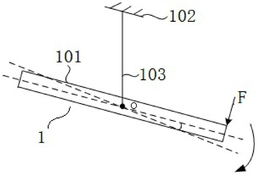
[0048] This embodiment proposes a torsion test device based on differential capacitance, such as Figure 1~4 As shown, it is a structural schematic diagram of the torsion testing device based on the differential capacitance and the torsion structure of the present embodiment.

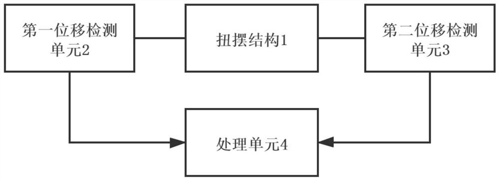
[0049] The torsion test device based on differential capacitance proposed in this embodiment includes a torsion structure 1, a first displacement detection unit 2, a second displacement detection unit 3, and a processing unit 4, wherein:

[0050] The torsion structure 1 is used to receive the micro-thrust generated by the external propeller;

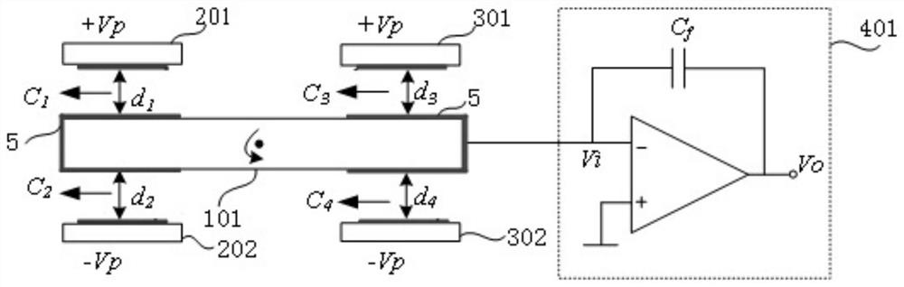
[0051] The first displacement detection unit 2 is used to detect the first displacement signal S of the torsion structure 1 1 The first displacement detection unit 2 is arranged at one end of the torsion structure 1, including a first capacitor plate 201 and a second capacitor plate 202, and the first capacitor plate 201 and the second capacitor plate 202 are res...

Embodiment 2

[0084]This embodiment proposes a method for reading the torsion decoupling based on the differential capacitance, and applies the torsion test device based on the differential capacitance proposed in Embodiment 1, such as Figure 6 As shown in , it is a flow chart of the reading method of torsion decoupling based on differential capacitance in this embodiment.

[0085] The differential capacitance-based torsion decoupling reading method proposed in this embodiment includes the following steps:

[0086] S1: When the external force signal acts on the torsion structure 1, the first displacement detection unit 2 and the second displacement detection unit 3 mounted on the torsion structure 1 respectively generate the first displacement signal S 1 and the second displacement signal S 2 ;

[0087] S2: The first displacement signal S 1 and the second displacement signal S 2 Processing is performed to decouple the rotational displacement signal and the translational displacement si...


PUM


Abstract

In order to overcome the defect that the coupling of a translational displacement signal and a torsional displacement signal generated by a suspension type torsional pendulum structure in a test affects the test precision, the invention provides a torsional pendulum test device based on a differential capacitor and a torsional pendulum decoupling reading method based on the differential capacitor. When an external force signal acts on the torsional pendulum structure, differential carriers are added to the first displacement detection unit and the second displacement detection unit, the positive and negative of the carriers are further adjusted, and the first displacement detection unit and the second displacement detection unit generate a first displacement signal S1 and a second displacement signal S2 respectively; and the first displacement signal S1 and the second displacement signal S2 are processed, and a rotation displacement signal and a translation displacement signal generated by the torsional pendulum structure are decoupled to obtain a rotation displacement signal and / or a translation displacement signal subjected to noise suppression, so that the torsional pendulum test precision can be effectively improved.

Description

technical field [0001] The present invention relates to the technical field of torsion testing, and more particularly, to a torsion testing device based on differential capacitance and a torsion decoupling reading method. Background technique [0002] With the continuous increase of human space science activities, there are more and more aircraft in space, and the structure is more and more complex, and the requirements for the performance of the aircraft are getting higher and higher. As a thruster that provides power for space vehicles, high-precision space science experiments put forward the requirement of "providing thrust with a resolution of micro-Newton level". The high-precision thrust measurement device is used for ground testing and evaluation of the performance of the micro-thrust, including the precise measurement of the resolution of the micro-thrust generated by the thruster, the thrust range and the dynamic performance of the micro-thrust, so as to ensure a gr...

Claims


Application Information

Patent Timeline
IPC IPC(8): G01L5/00
CPCG01L5/0038
Inventor 李祝张宪邹恕程郑文韬王观芳刘祺刘建平杨山清涂良成
Owner SUN YAT SEN UNIV
Features
  • Generate Ideas
  • Intellectual Property
  • Life Sciences
  • Materials
  • Tech Scout
  • Unparalleled Data Quality
  • Higher Quality Content
  • 60% Fewer Hallucinations
Learn More