Detection system for microscopic examination of microscope integrated with dyeing function

A detection system and microscope technology, which is applied in the field of microscope inspection detection system, can solve problems such as low degree of automation, influence on dyeing quality, and system aging, so as to improve accuracy and work efficiency, ensure quality and inspection effect, and avoid The effect of vibration damage

Pending Publication Date: 2021-09-28
上海宏勃生物科技发展有限公司
View PDF0 Cites 2 Cited by
  • Summary
  • Abstract
  • Description
  • Claims
  • Application Information

AI Technical Summary

Problems solved by technology

Factors such as the method of staining, the time of staining, and the technique of staining will directly affect the quality of staining, thereby affecting the accuracy of diagnosis during clinical testing.
At present, the vast majority of dyeing work is manual operation, and many unavoidable problems have occurred in the long-term artificial dyeing work, such as, the dyeing workflow is not standardized, the dyeing quality is uneven, the dyeing work efficiency is not high, and the dyeing solution is not stable. Pollution caused by improper use and physical injury to operators
At present, the dyeing instruments on the market are also troubled by the problems of low accuracy, low operational flexibility, and low degree of automation.
[0003] In the routine clinical inspection work of the hospital, staining and microscopic examination are operated separately, which is not only limited to the problems existing in the staining work, but also suffers from the aging of the system, low shooting accuracy, and low degree of automation of the microscopic examination analysis system. Limitation, unable to fundamentally improve the accuracy and efficiency of inspection

Method used


Image

  • Detection system for microscopic examination of microscope integrated with dyeing function
  • Detection system for microscopic examination of microscope integrated with dyeing function
  • Detection system for microscopic examination of microscope integrated with dyeing function

Examples


Embodiment Construction

[0023] The following will clearly and completely describe the technical solutions in the embodiments of the present invention with reference to the accompanying drawings in the embodiments of the present invention. Obviously, the described embodiments are only some, not all, embodiments of the present invention. Based on the embodiments of the present invention, all other embodiments obtained by persons of ordinary skill in the art without making creative efforts belong to the protection scope of the present invention.

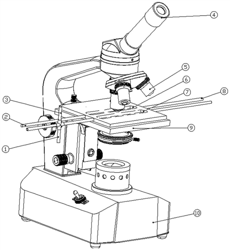
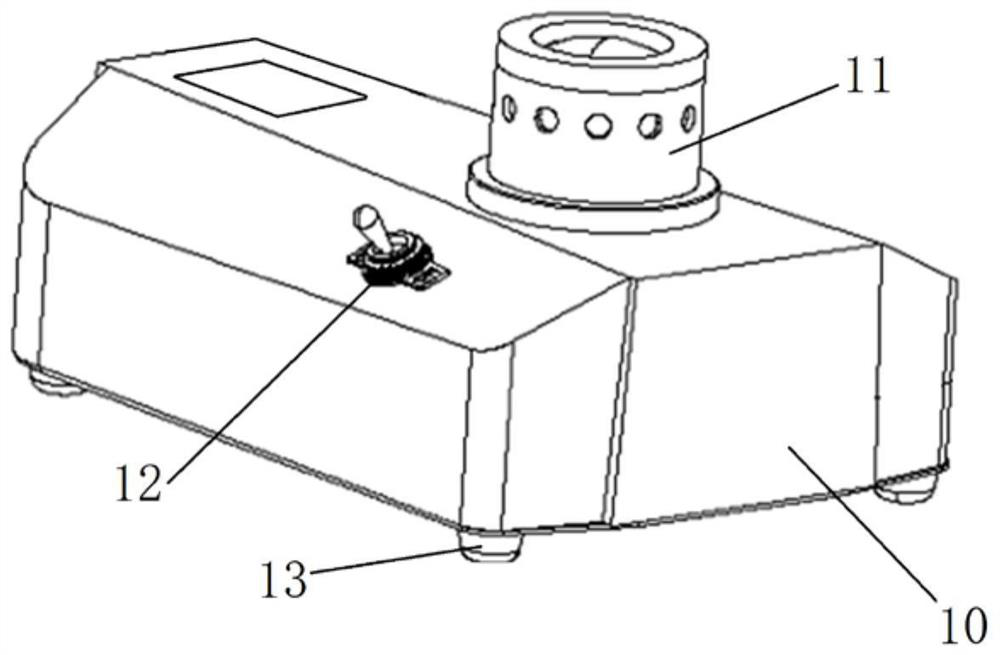
[0024] as attached figure 1 Shown, a kind of detection system of the microscopic inspection of the microscope integrated with dyeing function, comprises microscope group and staining group, and described microscope group comprises frame 10, stage 9, eyepiece and camera group 4, objective lens group 5, described Objective lens group 5 comprises more than two objective lenses of different optical lengths, and the camera group in the eyepiece and camera group 4 i...


PUM


Abstract

The invention discloses a detection system for microscopic examination of a microscope integrated with a dyeing function. The detection system comprises a display rack, an objective table, an eyepiece and camera group, an objective lens group, a dye liquor reagent sample introduction tube, a test sample introduction tube, an eluent sample introduction tube, a sample discharge tube, an undyed counting chamber, a dyed counting chamber and a glass slide. The objective lens group is mounted on the rack, the eyepiece and camera group is mounted right above the objective lens group, the objective table is mounted right below the objective lens group, and the undyed counting chamber, the dyed counting chamber, the glass slide, the dye liquor reagent sample introduction tube, the test sample introduction tube, the eluent sample introduction tube and the sample discharge tube are arranged above the objective table. The dye liquor reagent sample introduction tube, the test sample introduction tube and the eluent sample introduction tube are mounted at the left end of the objective table, and the sample discharge tube is mounted at the right end of the objective table. According to the invention, integration and full automation of dyeing and microscopic examination in clinical examination work are realized, the working accuracy and working efficiency are improved, and the dyeing quality and the examination effect are ensured.

Description

technical field [0001] The invention relates to the technical field of detection systems for microscope inspection, in particular to a detection system for microscope inspection integrated with a staining function. Background technique [0002] The formed components such as bacteria, insect eggs and cells that need to be tested in clinical testing are small, colorless and transparent. In order to be able to clearly and accurately observe and study these formed components, it is generally necessary to use relevant dyes to color these formed components Then observe its size and shape structure and other information through a microscope. Factors such as the method of staining, the time of staining, and the technique of staining will directly affect the quality of staining, thereby affecting the accuracy of diagnosis during clinical testing. At present, the vast majority of dyeing work is manual operation, and many unavoidable problems have arisen in the long-term artificial dy...

Claims


Application Information

Patent Timeline
Patent Type & Authority Applications(China)
IPC IPC(8): G01N1/31G01N21/84G01N21/01G02B21/02G02B21/24G02B21/06G02B21/34G02B21/36
CPCG01N1/31G01N21/84G01N21/01G02B21/02G02B21/248G02B21/06G02B21/34G02B21/36G01N2021/0112
Inventor 赵国军张嘉桐刘律文张帅李昂陈健
Owner 上海宏勃生物科技发展有限公司
Why Eureka
Try Eureka