
Quick-connection type combined cable joint based on power equipment and combination method thereof

A technology for combining cables and power equipment, applied in the direction of cable joints, etc., can solve the problems of loosening of the fastening structure, reducing the reliability of the desiccant inside the cable joint box, lack of anti-loosening structure, etc., so as to improve the firmness and reliability. Sexuality, improve the effect of warning effect

Inactive Publication Date: 2021-09-28
祖丹锋
View PDF1 Cites 1 Cited by
  • Summary
  • Abstract
  • Description
  • Claims
  • Application Information

AI Technical Summary

Problems solved by technology

[0005] In order to solve the above technical problems, the present invention provides a quick-connect combined cable joint based on power equipment and its combination method, to solve the problem that although the current combined cable joint can quickly connect the cable conductors, and can be connected by fastening The structure fastens the cable sheath on the box body, but the fastening structure on the cable joint lacks an effective anti-loosening structure, and the fastening structure is prone to loosening when the cable is subjected to external wind, etc., and the existing cable Although a desiccant can be placed inside the connector box to avoid moisture, mildew, and corrosion of the cable conductors inside the cable connector box, the desiccant needs to be replaced after it fails, and it is difficult for people to find the desiccant when repairing the inside of the cable connector box. The use of the situation, thereby reducing the reliability of the desiccant inside the cable joint box

Method used


Image

  • Quick-connection type combined cable joint based on power equipment and combination method thereof
  • Quick-connection type combined cable joint based on power equipment and combination method thereof
  • Quick-connection type combined cable joint based on power equipment and combination method thereof

Examples


Embodiment

[0033] as attached figure 1 to attach Figure 7 Shown:

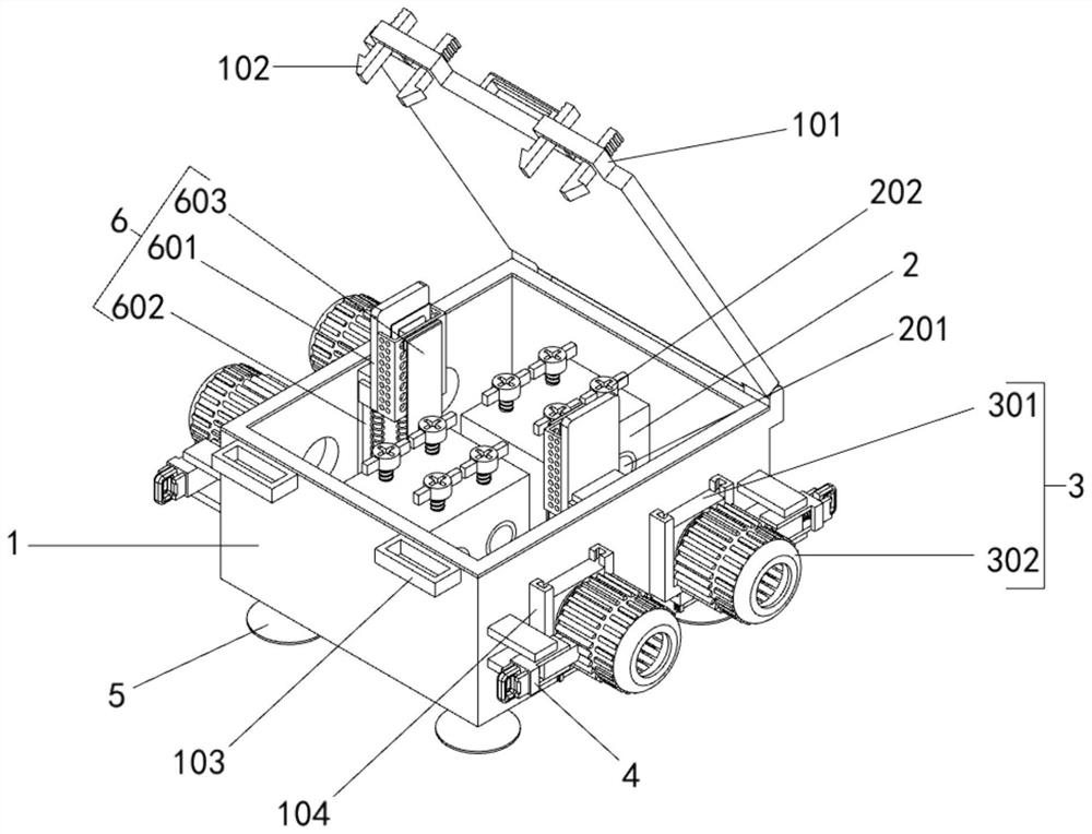
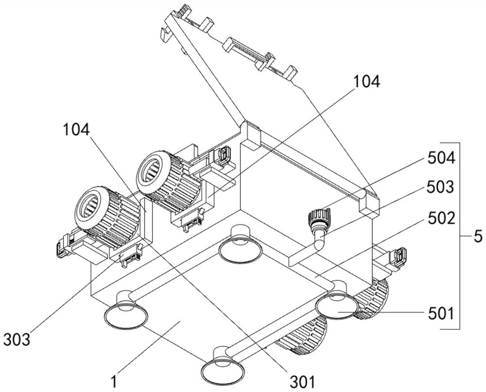
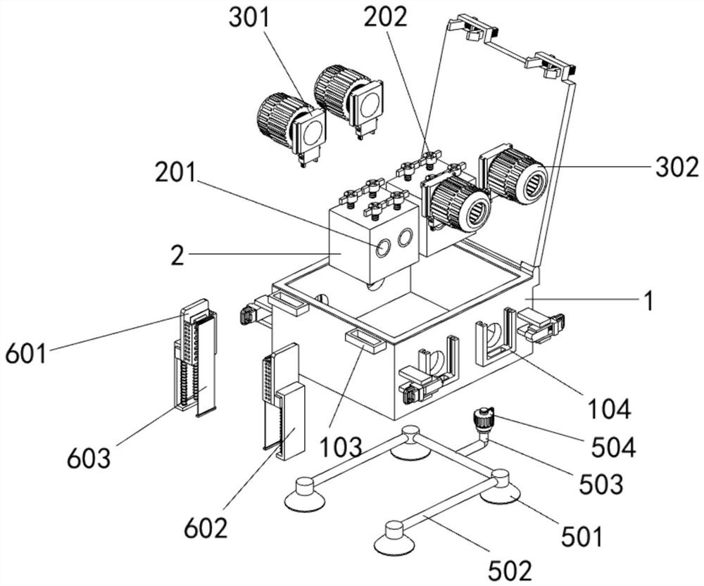
[0034] The present invention provides a quick-connect combined cable joint based on electric equipment and its combination method, comprising: a box body 1; two conductor connectors 2 are arranged on the inner bottom surface of the box body 1 in a symmetrical front and rear; the box body 1 includes Buckle supporting block 101, the first buckle 102, the snap-in block 103, the connecting block 104 and the first dividing plate 105, the top of the box body 1 is connected with the lid through the rotation of the rotating shaft, and the front end of the lid is left-right symmetrical. A buckle support block 101, the top of the front end of the box body 1 is symmetrically arranged with two snap-in blocks 103, and the snap-in block 103 and the snap-in support block 101 are rectangular frame structures, and the inside width of the snap-in block 103 greater than the inner width of the buckle support block 101; each buckle support...


PUM


Abstract

The invention provides a quick-connection type combined cable joint based on power equipment and a combination method thereof, which belong to the technical field of cable joints, and aim to solve the problem that a fastening structure on an existing cable joint is very easy to loosen due to lack of an effective anti-loosening structure. The combined cable joint comprises a box body; two conductor connecting pieces are arranged on the bottom end face in the box body in a front-back symmetrical mode, and the two conductor connecting pieces are both of a square blocky structure. two through holes are symmetrically formed in the left end face and the right end face of the box body front and back, and two fastening mechanisms are arranged at the positions, located at the through holes, of the left end face and the right end face of the box body. Under the action that a right triangle limiting block at the head end of the square sliding column is in close contact with a circular bead limiting tooth on the outer peripheral surface of the threaded fastening cylinder, the threaded fastening cylinder cannot be loosened anticlockwise at the moment, and then the threaded fastening cylinder is not prone to loosening when the cable is subjected to external wind power and the like. And the connection firmness of the cable joint is greatly improved.

Description

technical field [0001] The invention belongs to the technical field of cable joints, and more specifically relates to a quick-connect combined cable joint based on electric equipment and a combination method thereof. Background technique [0002] Power equipment includes two categories: power generation equipment and power supply equipment. Power generation equipment is mainly power plant boilers, steam turbines, gas turbines, water turbines, generators, transformers, etc. Power supply equipment is mainly transmission lines of various voltage levels, transformers, contactors wait. When electrical equipment transmits electrical energy, it needs to be transported through cables, and combined cable joints are generally used when connecting cable conductors. [0003] For example, application number: CN201810141055.2 A cable joint (16), including a housing (102), which has a channel (106), the channel is configured to hold the first signal conductor (406) of the first cable (14)...

Claims


Application Information

Patent Timeline
IPC IPC(8): H02G15/16
CPCH02G15/16
Inventor 祖丹锋
Owner 祖丹锋
Learn More