Building engineering round pipe bending device

A pipe bending device and technology for construction engineering, applied in the field of construction pipe bending, can solve problems such as low operation efficiency and limited pipe diameter range, and achieve the effects of improving efficiency, improving quality and improving accuracy

Inactive Publication Date: 2021-10-01
罗耀谊
View PDF0 Cites 0 Cited by
  • Summary
  • Abstract
  • Description
  • Claims
  • Application Information

AI Technical Summary

Problems solved by technology

[0003] However, the current existing pipe bending devices usually use a pipe diameter corresponding to a bending die and bending die, and often for pipes with slightly different pipe diameters, the bending die can be replaced to achieve bonding with the outer wall of the pipe, and then The rotation of the bending mold is used to bend the pipe to realize the bending operation of the pipe. In summary, the existing pipe bending device has the problem that it can only bend the pipe within a certain diameter range, and the bending operation is performed once at the same time. Only one pipe can be bent, resulting in low bending operation efficiency on the one hand, and limited range of applicable pipe diameters on the other hand

Method used


Image

  • Building engineering round pipe bending device
  • Building engineering round pipe bending device
  • Building engineering round pipe bending device

Examples


Embodiment

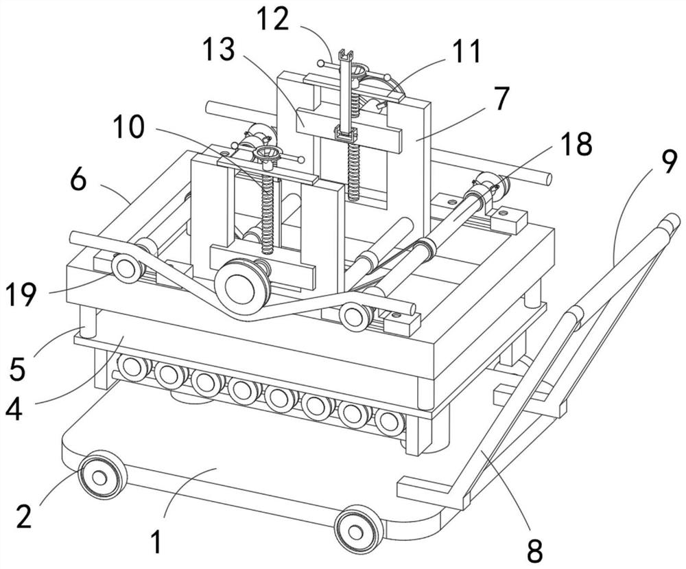
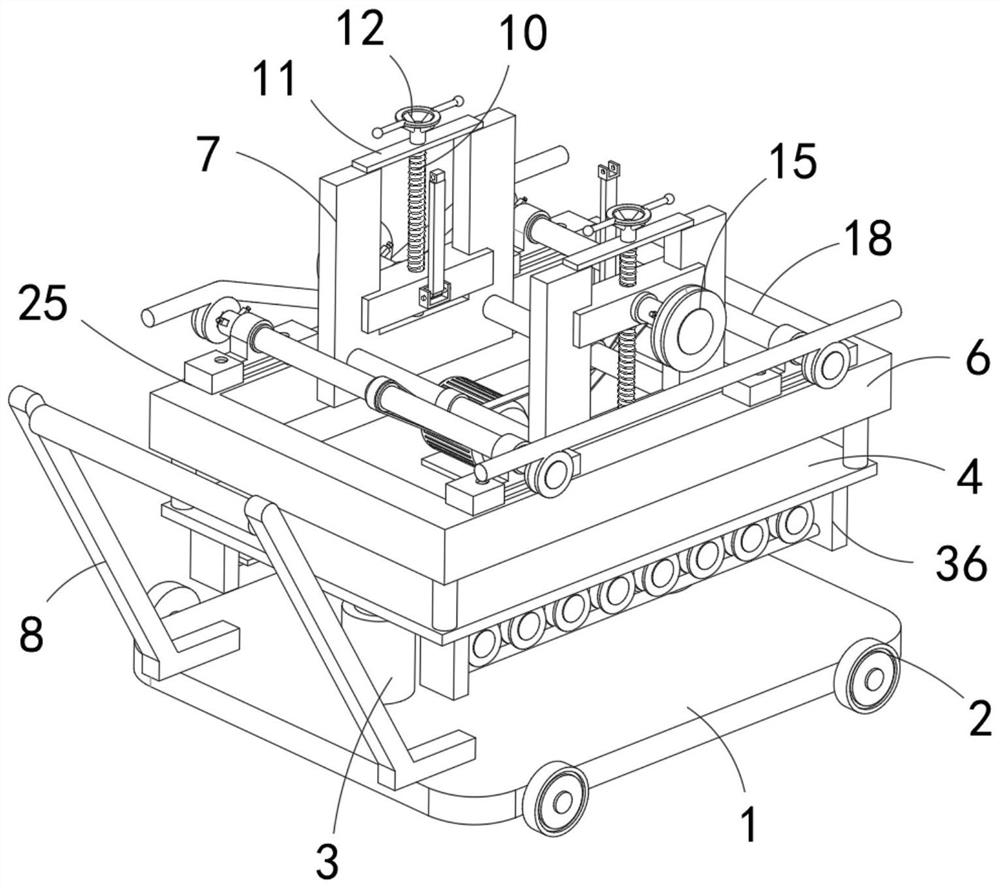
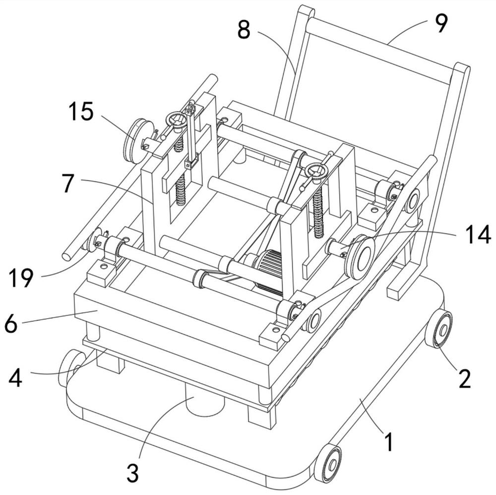
[0036] refer to Figure 1-8 , a round pipe bending device for construction engineering, comprising a base plate 1 and a push mechanism, the push mechanism is connected to the upper end of the base plate 1, the front and rear side walls of the base plate 1 are rotatably connected with rollers 2 contacting the ground, and the push mechanism includes two A tilting rod 8 fixedly connected to the upper end of the base plate 1, and a horizontal push rod 9 is fixedly connected between the side walls of the two tilting rods 8 away from the base plate 1, under the cooperative use of the pushing mechanism and a plurality of rollers 2, it can The overall position of the device is adjusted, which improves the maneuverability of the device and is convenient for the operator to bend the pipe.

[0037]Wherein, the upper end of the base plate 1 is fixedly connected with a hydraulic rod 3, and the telescopic end of the hydraulic rod 3 is fixedly connected with a support plate 4, and the upper ...


PUM


Abstract

The invention belongs to the technical field of building pipe bending, and particularly relates to a building engineering round pipe bending device. The building engineering round pipe bending device comprises a bottom plate and a pushing mechanism, the pushing mechanism is connected to the upper end of the bottom plate, rolling wheels making contact with the ground are rotationally connected to the front side wall and the rear side wall of the bottom plate, and a hydraulic rod is fixedly connected to the upper end of the bottom plate. The telescopic end of the hydraulic rod is fixedly connected with a supporting plate, the upper end of the supporting plate is fixedly connected with a plurality of vertical supporting rods, the upper ends of the supporting rods are fixedly connected with the same rectangular frame, two opposite U-shaped supports are fixedly connected to the inner wall of the rectangular frame, and movable bending mechanisms are arranged in notches of the U-shaped supports. Guide limiting mechanisms for bearing and conveying pipe fittings are arranged at the upper end of the rectangular frame on the two sides of the U-shaped supports. According to the building engineering round pipe bending device, when pipe fittings with different sizes are subjected to pipe bending operation, quick replacement can be carried out to meet the use requirement of the pipe fittings with different sizes, the pipe bending application range of the device is widened, and the pipe bending efficiency is relatively improved.

Description

technical field [0001] The invention relates to the technical field of building pipe bending, in particular to a round pipe bending device for construction engineering. Background technique [0002] During building construction, bending equipment is often used to bend some workpieces, such as steel bars, steel pipes, etc. In the existing technology, it is generally a vertical structure design. Although such a structure can well meet the requirements of bending pipes . [0003] However, the current existing pipe bending devices usually use a pipe diameter corresponding to a bending die and bending die, and often for pipes with slightly different pipe diameters, the bending die can be replaced to achieve bonding with the outer wall of the pipe, and then The rotation of the bending mold is used to bend the pipe to realize the bending operation of the pipe. In summary, the existing pipe bending device has the problem that it can only bend the pipe within a certain diameter rang...

Claims


Application Information

Patent Timeline
Patent Type & Authority Applications(China)
IPC IPC(8): B21D7/08B21D7/16B21D43/00B21D43/08
CPCB21D7/08B21D7/16B21D43/006B21D43/08
Inventor 罗耀谊
Owner 罗耀谊
Why Eureka
Try Eureka