Supercharge Your Innovation With Domain-Expert AI Agents!

Clamping device for welding and robot

A technology of clamping mechanism and clamping parts, which is applied in the direction of auxiliary devices, welding equipment, auxiliary welding equipment, etc., can solve the problems of welding robot surface damage and low workpiece positioning accuracy, achieve welding efficiency, improve welding efficiency, and ensure The effect of welding precision

Inactive Publication Date: 2021-10-01
NANJING NIEBO INTERNET OF THINGS TECH CO LTD
View PDF0 Cites 0 Cited by
  • Summary
  • Abstract
  • Description
  • Claims
  • Application Information

AI Technical Summary

Problems solved by technology

[0004] These two methods have their own advantages: the first operation method has higher workpiece positioning accuracy, but when the welding robot welds the workpiece from below, the high-temperature residue during the welding process will impact the welding robot, causing surface damage to the welding robot; the second This operation method has low workpiece positioning accuracy, but it can protect the welding robot very well

Method used


Image

  • Clamping device for welding and robot
  • Clamping device for welding and robot
  • Clamping device for welding and robot

Examples


Embodiment 1

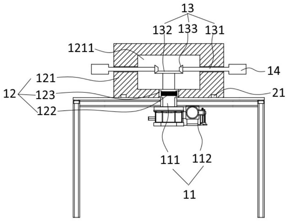
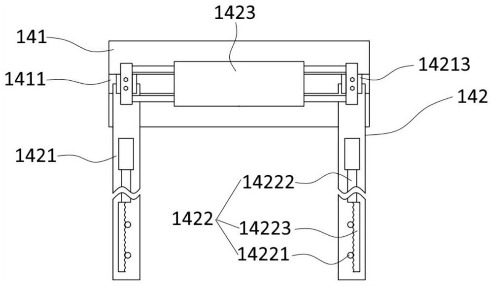
[0053] combine figure 1 and figure 2 The clamping device 1 for welding provided in this embodiment includes a driving mechanism 11 , a first rotating mechanism 12 , a second rotating mechanism 13 and a clamping mechanism 14 .

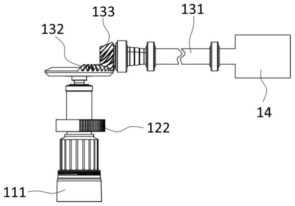
[0054] Specifically, the driving mechanism 11 includes a driving shaft 111 and a driving assembly 112 . The drive shaft 11 is arranged vertically. The bottom end of the drive shaft 11 is connected with the drive assembly 112 to realize circumferential rotation. The drive assembly 112 includes a drive motor and a reducer. The output end of the drive motor is connected to the input end of the reducer to output power, and the output end of the reducer is coaxially connected to the drive shaft 111 to realize deceleration and drive the drive shaft 111 to rotate at a low speed.

[0055] The first rotating mechanism 12 is connected with the drive shaft 111 to realize intermittent rotation in the horizontal plane. The first rotating mechanism 12 includes ...

Embodiment 2

[0066] combine Figure 5 , this embodiment provides a robot for welding. The robot includes a gripping device 1 , a working platform 2 , a mechanical arm 3 and a welding torch 4 .

[0067] Specifically, the clamping device 1 adopts the clamping device 1 for welding in the first embodiment, and its specific structure has been described in detail in the first embodiment, and will not be repeated here.

[0068] The working platform 2 is arranged horizontally, and several supporting frames 5 are arranged at the bottom thereof. The shell of the reducer is fixedly connected with the bottom surface of the working platform 2, and the bottom end of the drive shaft 111 penetrates the working platform 2 downwards and is fixedly connected with the output end of the reducer. The rotating part 121 is placed flat on the top surface of the working platform 2. In order to ensure the stability of the rotating part 121 rotation, the working platform 2 is provided with an annular guide rail 21,...


PUM


Abstract

The invention discloses a clamping device for welding and a robot, and belongs to the technical field of welding equipment. The clamping device comprises a driving mechanism, a first rotating mechanism, a second rotating mechanism and a clamping mechanism. The driving mechanism drives a first rotating mechanism to achieve horizontal circumferential intermittent rotation, and the first rotating mechanism drives a clamping mechanism clamping a workpiece to rotate horizontally, circumferentially and intermittently through a second rotating mechanism so as to realize overlapping of a plurality of welding procedure processes, so that the welding efficiency is improved. Meanwhile, the driving mechanism drives the second rotating mechanism to circumferentially and intermittently rotate in a vertical plane, so that the clamping mechanism drives the workpiece to turn over, and therefore, the front face and the back face of the workpiece are welded. Compared with the prior art, through linkage of the first rotating mechanism and the second rotating mechanism, the welding efficiency can be improved, and the welding robot can be protected under the condition that the welding precision is ensured.

Description

technical field [0001] The invention belongs to the technical field of welding equipment, in particular to a clamping device and a robot for welding. Background technique [0002] Welding equipment refers to the equipment needed to realize the welding process. Among them, thanks to the characteristics of high welding precision and high efficiency, welding robots are more and more widely used in the welding field. [0003] In the prior art, in order to improve the welding quality, it is usually necessary to weld the front and back sides of the workpiece to be welded. In this case, there are two methods of operation: one is to weld the top surface of the workpiece from above with the welding robot, and then weld the bottom surface of the workpiece from below with the welding robot; the other is to weld the workpiece from above with the welding robot The workpiece is welded, and after one side is welded, the workpiece is taken out, then turned over and welded on the other sid...

Claims


Application Information

Patent Timeline
IPC IPC(8): B23K37/047B25J11/00B25J9/04
CPCB23K37/047B25J11/00B25J9/04
Inventor 郭晓艳王微李贤平
Owner NANJING NIEBO INTERNET OF THINGS TECH CO LTD
Features
  • R&D
  • Intellectual Property
  • Life Sciences
  • Materials
  • Tech Scout
  • Unparalleled Data Quality
  • Higher Quality Content
  • 60% Fewer Hallucinations
Learn More