Brick press with convenient material distributing and discharging functions
A brick press and cloth technology, which is applied in the field of brick presses, can solve the problems of pushing out bricks that cannot be pressed, and unable to automatically distribute bricks, etc., and achieves the effect of avoiding hand injury.
- Summary
- Abstract
- Description
- Claims
- Application Information
AI Technical Summary
Problems solved by technology
Method used
Image

Examples
Embodiment 1
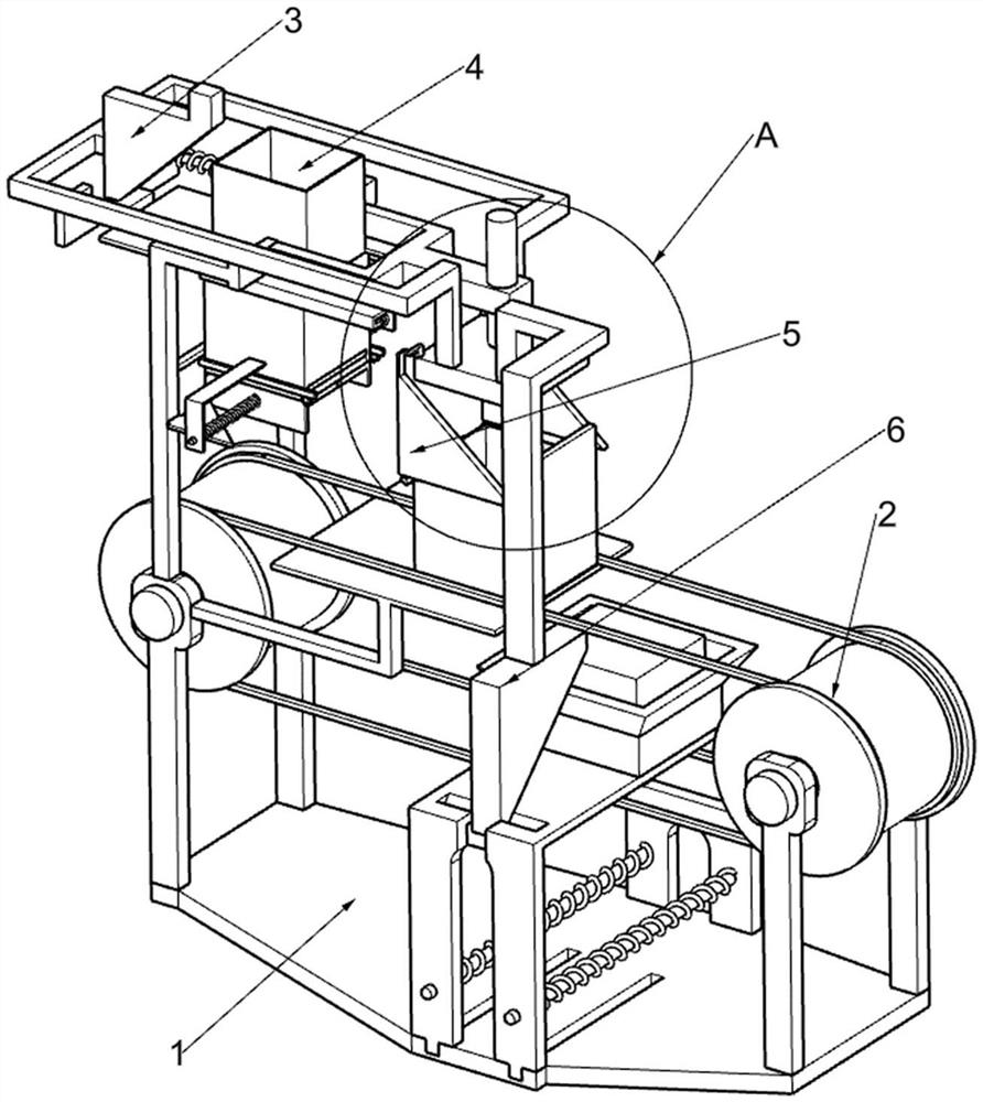
[0028] A brick press that is convenient for cloth and discharge, such as Figure 1-11 As shown, it includes a supporting frame 1, a brick pressing mechanism 2, a reciprocating mechanism 3 and a material distribution mechanism 4. The brick material on the material frame 26 is compacted, and the brick pressing mechanism 2 is provided with a reciprocating mechanism 3, and the support shelf 1 is provided with a material distribution mechanism 4, and the material distribution mechanism 4 is used for cloth brick material.
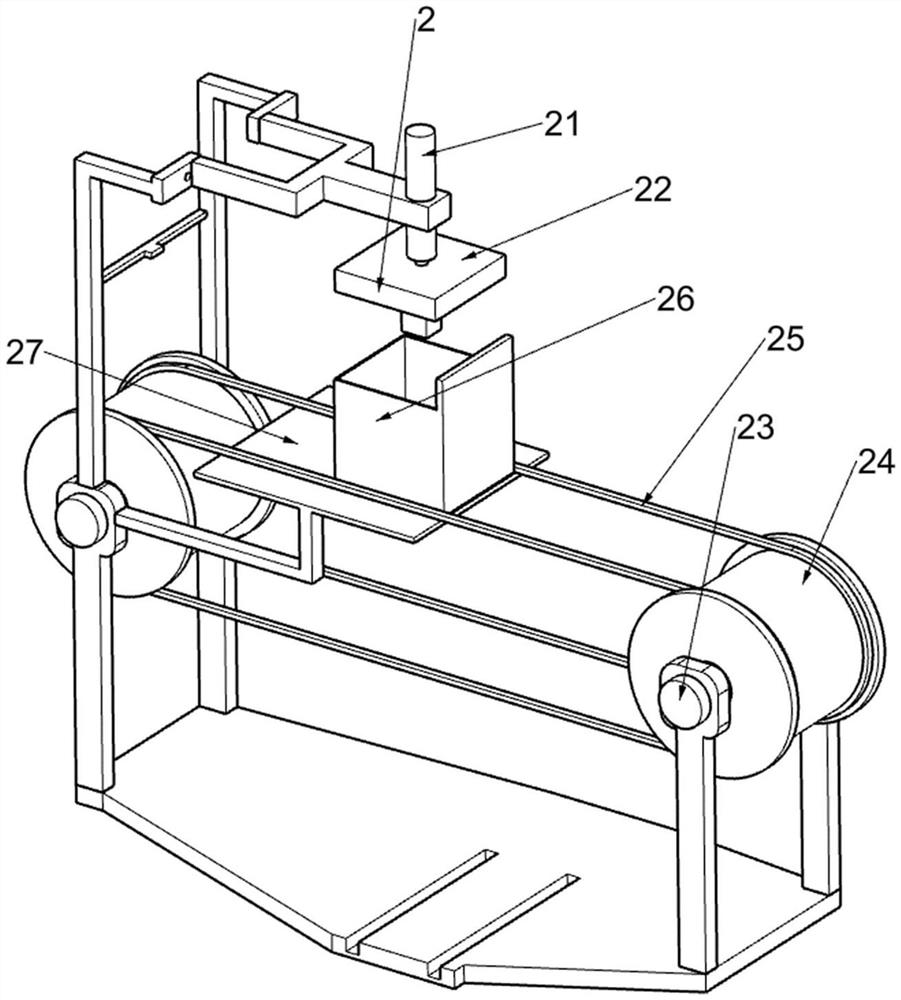
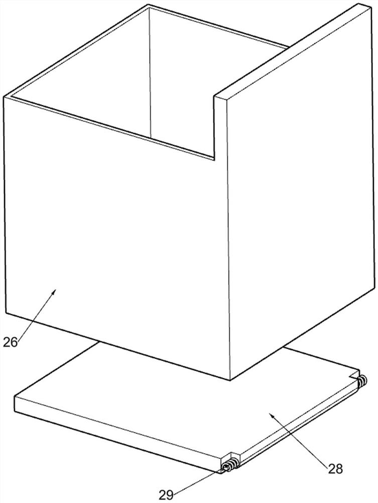
[0029] The brick pressing mechanism 2 includes an electric push rod 21, a pressing block 22, a rotating shaft 23, a rotating wheel 24, a rotating bar 25, a charging frame 26, a first fixed plate 27, a rotating plate 28 and a first torsion spring 29, supporting The shelf 1 is provided with an electric push rod 21, and the electric push rod 21 is used to drive the compression block 22 and its upper device to reciprocate up and down. The brick material on one of th...
Embodiment 2
[0036] On the basis of Example 1, such as Figure 8-10 As shown, a pushing mechanism 5 is also included, and the pushing mechanism 5 is arranged on the brick pressing mechanism 2. The pushing mechanism 5 is used to push the rotating block 53 and its upper device to move in a direction away from the second fixed plate 43. The pushing mechanism 5 includes The 3rd wedge-shaped plate 51, the 3rd fixed mount 52, the rotating block 53, the second torsion spring 54 and the stop frame 55, the pressing block 22 is provided with a pair of the 3rd wedge-shaped plate 51, the 3rd wedge-shaped plate 51 is used for promoting the rotating block 53 and its upper device move towards the direction away from the second fixed plate 43, and the charging frame 26 is provided with a pair of third fixed mounts 52, and the third fixed mount 52 is rotatably connected with a rotating block 53, and the rotating block 53 is connected with Two second torsion springs 54, the second torsion springs 54 are use...
Embodiment 3
[0039] On the basis of Example 2, such as Figure 11 As shown, a discharge mechanism 6 is also included, and the discharge mechanism 6 is arranged on the support frame 1. The discharge mechanism 6 includes a fourth fixed mount 61, a fourth wedge-shaped plate 62, a second sliding frame 63, and a fifth fixed mount. 64, the third slide bar 65, the fourth return spring 66 and the fixed frame 67, the pressing block 22 is provided with a fourth fixed frame 61, the fourth fixed frame 61 is used to drive the fourth wedge-shaped plate 62 to move, the fourth fixed frame 61 is provided with a fourth wedge-shaped plate 62, the fourth wedge-shaped plate 62 is used to extrude the second sliding frame 63 and its upper device to move towards the direction close to the fifth fixed frame 64, and the supporting frame 1 is slidably connected with a second sliding frame. frame 63, the second sliding frame 63 is in contact with the fourth wedge-shaped plate 62, the fifth fixed frame 64 is fixedly c...
PUM
 Abstract
Description
Claims
Application Information
 - R&D
- Intellectual Property
- Life Sciences
- Materials
- Tech Scout
- Unparalleled Data Quality
- Higher Quality Content
- 60% Fewer Hallucinations
Browse by: Latest US Patents, China's latest patents, Technical Efficacy Thesaurus, Application Domain, Technology Topic, Popular Technical Reports.
© 2025 PatSnap. All rights reserved.Legal|Privacy policy|Modern Slavery Act Transparency Statement|Sitemap|About US| Contact US: help@patsnap.com