
Wire and cable winding device

A wire and cable winding device technology, which is applied in the field of cables, can solve the problems of a single diameter of the winding roller, the inability to remove dust and impurities, and the inability to ensure the cleanliness of the wire or cable surface, etc., to achieve a wide range of applications

Pending Publication Date: 2021-10-01
宋凯
View PDF0 Cites 0 Cited by
  • Summary
  • Abstract
  • Description
  • Claims
  • Application Information

AI Technical Summary

Problems solved by technology

However, the diameters of the inner chambers of different rolls are often different. The existing winding devices cannot fix the rolls with different diameters on them and drive them to rotate for winding. The diameters of the applicable rolls are fixed and Single, unable to meet the needs of different caliber and size reeling rolls; at the same time, the existing reeling device cannot clean the dust and impurities on the wire or cable, and cannot guarantee the cleanliness of the wire or cable surface after rewinding; and, After the winding is completed, the wire or cable needs to be cut manually, and the wire or cable cannot be cut automatically, which increases the labor intensity and is cumbersome to operate

Method used


Image

  • Wire and cable winding device
  • Wire and cable winding device
  • Wire and cable winding device

Examples


Embodiment Construction

[0022] The present invention will be clearly and completely described below in conjunction with the accompanying drawings.

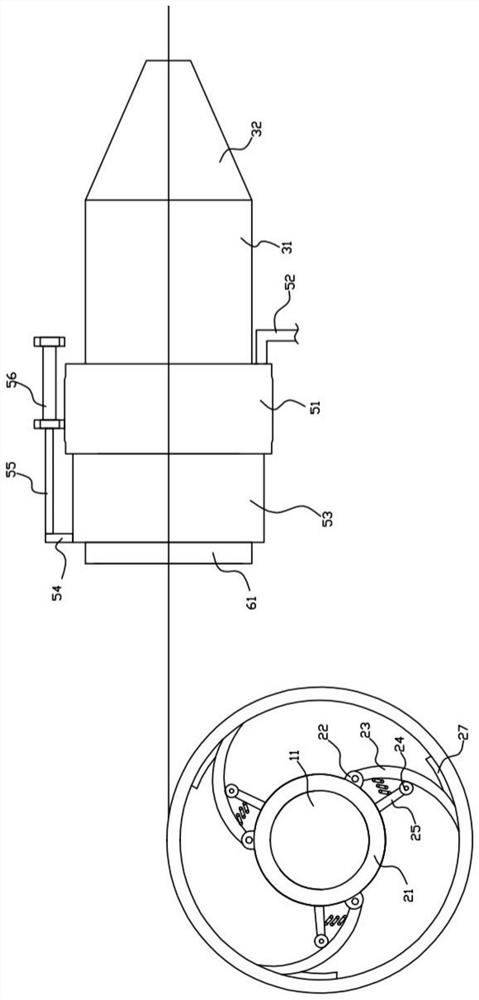
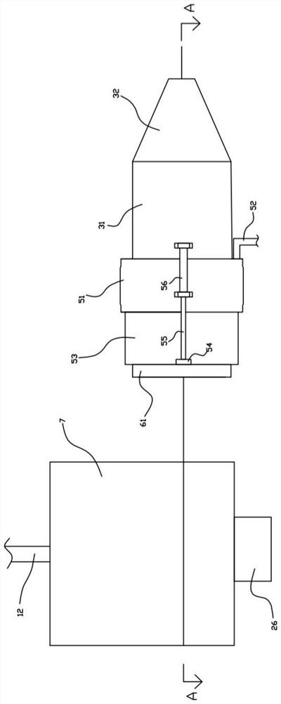
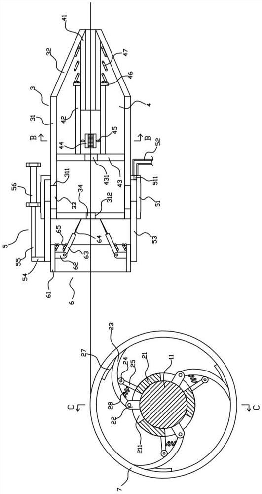
[0023] Such as Figure 1 to Figure 5 As shown, the wire and cable winding device of the present invention includes a driving structure 1, a supporting and fixing structure 2 disposed on the driving structure 1, a housing structure 3 disposed on one side of the driving structure 1, and a housing structure 3 disposed on the housing. The dust removal structure 4 inside the structure 3 , the air intake structure 5 arranged outside the shell structure 3 , and the cutting structure 6 arranged on the air inlet structure 5 .

[0024] Such as Figure 1 to Figure 3 and Figure 5As shown, the driving structure 1 includes a driving roller 11, a rotating shaft 12 arranged at one axial end of the driving roller 11, a driving block 13 arranged at the other end of the driving roller 11, and a driving block 13 arranged at the axial end of the driving block 13. The con...


PUM


Abstract

The invention relates to the technical field of electric wires and cables, in particular to an electric wire and cable winding device. The device comprises a driving structure and a supporting and fixing structure, wherein the driving structure comprises a drive roller; the supporting and fixing structure further comprises a rotating frame, a connecting block, a supporting rod, a rolling wheel and a fixing rod; the drive roller is rotationally contained in the rotating frame; a first through hole is formed in the rotating frame; one end of the connecting block is fixedly connected with the outer circumferential face of the drive roller; the connecting block penetrates through the first through hole; one end of the fixing rod is fixedly connected with the outer circumferential face of the rotating frame; and the other end of the fixing rod is in pivot connection with the rolling wheel. The rotating frame sliding relative to the drive roller is arranged on the drive roller, so that the supporting rod rapidly rotates around the connecting block, the end, away from the connecting block, of the supporting rod rapidly abuts against the inner circumferential face of a winding roller, and stable fixing of the winding roller is achieved; and the device can adapt to the winding operation of the winding rollers with different calibers on electric wires and cables, is wide in application range, and can drive the winding rollers to rotate stably.

Description

technical field [0001] The invention relates to the technical field of cables, in particular to a wire and cable winding device. Background technique [0002] In the field of wire and cable, it is often necessary to roll the wire and cable onto a hollow roll for storage or transportation. However, the diameters of the inner chambers of different rolls are often different. The existing winding devices cannot fix the rolls with different diameters on them and drive them to rotate for winding. The diameters of the applicable rolls are fixed and Single, unable to meet the needs of different caliber and size reeling rolls; at the same time, the existing reeling device cannot clean the dust and impurities on the wire or cable, and cannot guarantee the cleanliness of the wire or cable surface after rewinding; and, After the winding is completed, the wire or cable needs to be cut manually, and the wire or cable cannot be cut automatically, which increases the labor intensity and is...

Claims


Application Information

Patent Timeline
Patent Type & Authority Applications(China)
IPC IPC(8): B65H54/54B65H54/70B65H54/71B65H67/08
CPCB65H54/543B65H54/702B65H54/71B65H67/081B65H2701/34
Inventor 不公告发明人
Owner 宋凯
Learn More