A core-shell composite tank

A core-shell and tank technology, applied in textiles and papermaking, filament/thread forming, fiber processing, etc., can solve problems such as single product structure, and achieve the effect of various product structures, rich forms, and strong adjustability

Active Publication Date: 2022-04-19
WUHAN TEXTILE UNIV
View PDF12 Cites 0 Cited by
  • Summary
  • Abstract
  • Description
  • Claims
  • Application Information

AI Technical Summary

Problems solved by technology

[0006] The purpose of the present invention is to overcome the defects and problems of single product structure existing in the prior art, and to provide a core-shell composite tank body with various product structures

Method used


Image

  • A core-shell composite tank
  • A core-shell composite tank
  • A core-shell composite tank

Examples


Embodiment 1

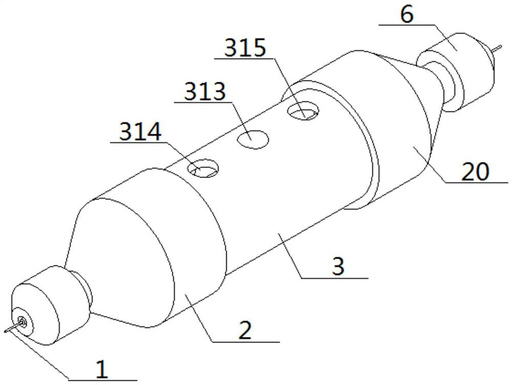
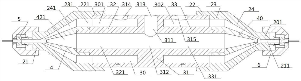
[0067] See Figure 1 — Figure 10 , a kind of core shell composite tank, comprising a tank body 3, the left outer nozzle 2 and the right outer nozzle 20, the internal of the tank body 3 is provided with a coaxial tank cavity 30, the left and right ends of the tank body 3 are connected to the left outer nozzle 2, the right outer nozzle 20, and the left and right ends of the tank cavity 30 are connected to the left outer nozzle 2, the inner cavity of the right outer nozzle 20 is connected; the internal of the tank body 3 is provided with a vertical axis of the tank body 31, The parts of the tank body 3 located on both sides of the pie body 31 are the left circumference cavity 301, the right circumferential cavity 302, the left circumferential cylindrical cavity 301, the inner portion of the right circumferential cylindrical cavity 302 respectively corresponding to the left cylinder 32, the right cylinder 32 of the inner end of the pie body 31 is connected, the outer end of the left c...

Embodiment 2

[0069] The basic content is the same as Example 1, the difference is that:

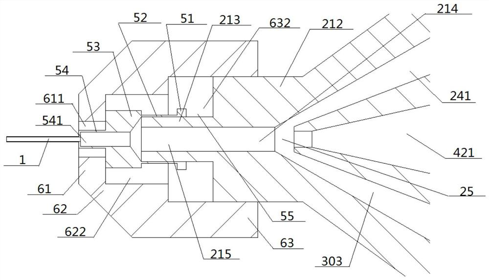
[0070] The structure of the left inner nozzle 4, the right inner nozzle 40 is consistent; the left inner nozzle 4 comprises an inner cylinder 41 and an inner cone 42, the inner end of the inner column 41 is socketed on the side circumference of the outer end of the left cylinder 32, the outer end of the inner cylinder 41 is connected to the large diameter end of the inner cone 42, and the small diameter end of the inner cone 42 extends outward; the inner cylinder 41 and the interior of the inner cone 42 are respectively opened with an inner column cavity 411 and an inner cone cavity 421, and the inner cone cavity 421 is connected to the left column cavity 321. The outer end of the left column 32, the outer end of the right column 33 is consistent; the outer end of the left column 32 includes a narrow column 322 and a wide column 323 located outside the left circumferential cavity 301, the diameter of the ...

Embodiment 3

[0072] The basic content is the same as Example 2, the difference is that:

[0073] The structure of the left external nozzle 2, the right outer nozzle 20 is consistent; the left external nozzle 2 includes an outer posterior column 22, an outer middle column 23, an outer anterior cone 24, and its interior corresponding to the opening of the outer posterior column cavity 221, the outer middle column cavity 231, the outer front cone cavity 241, the diameter of the outer posterior column cavity 221 is greater than the diameter of the outer middle column cavity 231, the outer posterior column cavity 221 is socketed on the outer side of the left end of the tank body 3, the two ends of the outer medial cylindrical cavity 231 are respectively and the left circumference cylindrical cavity 301, The large diameter end of the outer anterior cone cavity 241 is connected, the small diameter end of the outer front cone cavity 241 is connected to the inner nozzle cavity 211, and the nozzle chamb...


PUM


Abstract

A core-shell type composite tank body, including a tank body and left outer nozzles and right outer nozzles connected at both ends, wherein, the inside of the tank body is provided with a middle cake body perpendicular to the central axis of the tank body, and the inside of the tank body is The parts located on both sides of the middle cake body are the left and right pillar cavities respectively, and the insides of the left and right pillar cavities are respectively provided with left and right cylinders, and the outer ends of the left and right cylinders are connected to the left and right The right inner nozzle is connected correspondingly. The inside of the middle cake body is provided with a cake vertical cavity and a cake horizontal cavity. The middle feeding port is connected with the middle part of the cake horizontal cavity through the cake vertical cavity. The inner ends of the cavity are connected, the outer end of the inner cavity of the left column passes through the inner cavity of the left inner nozzle, the inner cavity of the left outer nozzle, and then communicates with the left nozzle, and the outer end of the inner cavity of the right column passes through the inner cavity of the right inner nozzle in turn. The inner chamber and the inner chamber of the right outer nozzle communicate with the right spray pipe. This design not only has a variety of product structures, but also has a higher quality of yarn, and has stronger adjustability and stronger firmness.

Description

Technical field [0001] The present invention relates to a spinning apparatus, belonging to the field of textile machinery, in particular to a core shell composite tank. Background [0002] Centrifugal spinning refers to the method by which the centrifugal and shear forces generated by the polymer melt or solution are thrown out of the fine holes by means of a high-speed rotating device to form fibers. [0003] The authorization announcement number is CN205617001U, the utility model patent with the authorization announcement date of October 5, 2016 discloses a centrifugal spinning device, which includes a motor, spinning head and collection rod, the spinning head is mounted on the top of the hinge of the motor and rotated by the motor, the spinning head has a cavity containing the spinning liquid, the top of the spinning head is provided with an injection port, the side wall of the spinning head is provided with a spray hole connected with the cavity, the collection rod is set ar...

Claims


Application Information

Patent Timeline
Patent Type & Authority Patents(China)
IPC IPC(8): D01D5/18D01D5/34
CPCD01D5/18D01D5/34
Inventor 张智明李文慧刘康梅顺齐吴紫俊
Owner WUHAN TEXTILE UNIV
Why Eureka
Try Eureka