Summer flood high-position flood discharge sluice

A high-level, flood technology, applied in water conservancy projects, marine engineering, coastline protection and other directions, can solve the problem of low intelligence of the gate, and achieve the effect of improving the intelligence, increasing the area, and restoring the convenient location.

Inactive Publication Date: 2021-10-01
王耀川
View PDF3 Cites 0 Cited by
  • Summary
  • Abstract
  • Description
  • Claims
  • Application Information

AI Technical Summary

Problems solved by technology

[0005] Aiming at the deficiencies of the prior art, the present invention provides a high-level flood discharge sluice in summer flood season, which solves the problem that the existing sluices have a low degree of intelligence and cannot use the water level to automatically control the opening of the sluice for flood discharge. It has strong protection ability and can Effectively protect the external parts of the gate, and can quickly restore the position to continue working next time

Method used


Image

  • Summer flood high-position flood discharge sluice
  • Summer flood high-position flood discharge sluice
  • Summer flood high-position flood discharge sluice

Examples


Embodiment 1

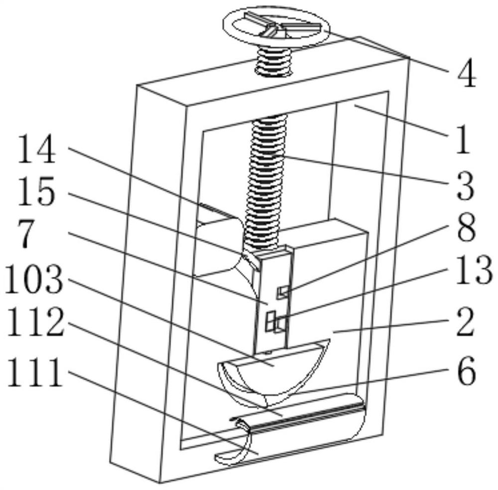
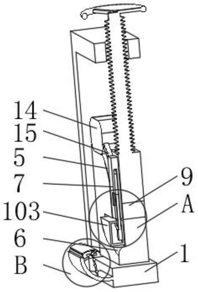
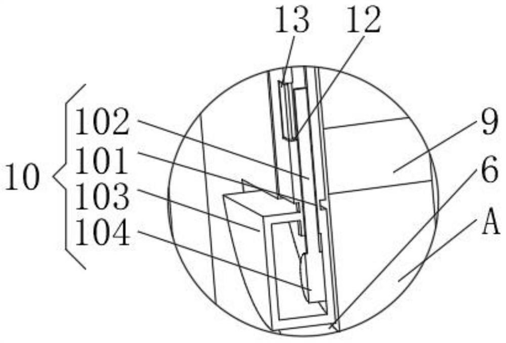
[0031] see Figure 1-3 , the present invention provides a technical solution: a high-level flood discharge gate in summer flood season, comprising a gate frame 1, a gate plate 2 is slidingly connected between the two sides of the inner wall of the gate frame 1, and a push-pull rod 3 is installed on the top of the gate plate 2. The pull rod 3 is a threaded rod. The end of the push-pull rod 3 penetrating to the outside of the gate frame 1 is equipped with a rotary handle 4. One side of the gate plate 2 is provided with a lifting groove 5. The bottom of the lifting groove 5 is connected with a limiting groove 6, and the limiting groove 6 A lifting plate 7 is slidably connected between the two sides of the inner wall of the lifting plate 7, and one side of the lifting plate 7 is provided with a flood discharge hole 8, and one side of the inner wall of the lifting groove 5 is provided with a drainage hole 9 that is compatible with the flood discharge hole 8. A control device 10 is ...

Embodiment 2

[0037] see Figure 1-4, the present invention provides a technical solution: on the basis of Embodiment 1, a protective device 11 is installed on one side of the gate frame 1, the protective device 11 includes a protective arc plate 111, and the top of the protective arc plate 111 is rotatably connected with a metal plate 112 One side of the arc protection plate 111 is located below the metal plate 112 and is fixedly connected with a rubber plate 113 .

[0038] The top of the protective arc plate 111 is fixedly connected with an elastic rope 16, and the end of the elastic rope 16 away from the protective arc plate 111 is fixedly connected with the metal plate 112, and the outside of the elastic rope 16 is uniformly equipped with a limit ball 17.

[0039] The top of the rubber plate 113 is provided with a guide hole 18, and a guide wheel 19 is installed between the two sides of the inner wall of the guide hole 18, and the elastic cord 16 and the limit ball 17 are all slidably c...

Embodiment 3

[0042] see Figure 1-5 , the present invention provides a technical solution: on the basis of Embodiment 1, an extension groove 20 is evenly opened on the outside of the limit ball 17, and an outside plate 21 and an inside plate 22 are uniformly installed inside the extension groove 20, and the outside plate 21 and The inner boards 22 are rotationally connected, and one side of the outer board 21 and the inner board 22 is fixedly connected with a foam board 23 .

[0043] Both the outer plate 21 and the inner plate 22 are connected by metal sheets 24 , and the bottoms of the outer plate 21 and the inner plate 22 are fixedly connected with counterweights 25 .

[0044] When in use, the limit airbag 103 squeezes the rubber plate 113 and the metal plate 112 to deflect away from the direction of the gate frame 1. After the elastic cord 16 is elongated, the limit ball 17 moves to the outside of the rubber plate 113 and extends to the inside of the groove 20. When water enters, the f...


PUM


Abstract

The invention discloses a summer flood high-position flood discharge sluice, and relates to the technical filed of sluices. The summer flood high-position flood discharge sluice comprises a sluice gate frame, a flashboard is slidably connected between the two sides of the inner wall of the sluice gate frame, a push-pull rod is installed at the top of the flashboard and is of a threaded rod, a rotating handle is installed at the end, penetrating out of the sluice gate frame, of the push-pull rod, a lifting groove is formed in one side of the flashboard, the bottom of the lifting groove communicates with a limiting groove, a lifting plate is slidably connected between the two sides of the inner wall of the limiting groove, a flood discharge hole is formed in one side of the lifting plate, and a drainage hole matched with the flood discharge hole is formed in one side of the inner wall of the lifting groove. According to the summer flood high-position flood discharge sluice, the purpose of improving the intelligence degree of a sluice gate is achieved, the sluice gate can be automatically controlled to be opened for flood discharge according to the height of the water level, the protection capacity is high, parts outside the sluice gate can be effectively protected, and the position can be quickly restored to facilitate next-time continuous work.

Description

technical field [0001] The invention relates to the technical field of sluices, in particular to a high-level flood discharge sluice in summer flood season. Background technique [0002] The gate is used to close and open the control facility of the discharge (discharging) channel, an important part of the hydraulic structure, which can be used to intercept the water flow, control the water level, adjust the flow, discharge sediment and floating objects, etc. [0003] However, the existing gates have a low degree of intelligence, and cannot use the water level to automatically control the gate to open for flood discharge. The protection ability is poor, and the external parts of the gate cannot be protected, and the position cannot be quickly restored to facilitate the next work. Contents of the invention [0004] (1) Solved technical problems [0005] Aiming at the deficiencies of the prior art, the present invention provides a high-level flood discharge sluice in summer...

Claims


Application Information

Patent Timeline
Patent Type & Authority Applications(China)
IPC IPC(8): E02B7/26E02B8/00
CPCE02B7/26E02B8/00
Inventor 王耀川
Owner 王耀川
Why Eureka
Try Eureka