Vehicle-mounted management and control flow dividing equipment
What is Al technical title?
Al technical title is built by PatSnap Al team. It summarizes the technical point description of the patent document.
A shunt equipment, control technology, applied in the direction of mechanical equipment, control valves, valve housing structures, etc., can solve the problems of wire bending, failure to meet localization requirements, and large sealing problems at splicing joints
Active Publication Date: 2021-10-01
衡阳泰豪通信车辆有限公司
View PDF7 Cites 0 Cited by
Summary
Abstract
Description
Claims
Application Information
AI Technical Summary
This helps you quickly interpret patents by identifying the three key elements:
Problems solved by technology
Method used
Benefits of technology
Problems solved by technology
The problem is that most of the main components are foreign brands, which cannot meet the requirements of localization
[0007] 4. In the specific connection process between the chip and the sensor wire in the background technology, the wire generally extends along the wire groove provided on the valve body or the electrical box, but for For the irregular valve body and the electrical box wall in the form of a square plate, its irregular or relatively large volume is not conducive to slotting, or requires a large-scale processing platform
[0008] 5. In the specific installation process of the chip and the sensor wire in the background technology, the wire is laid to the corresponding position of the chip interface and directly bent to align with the interface, which will cause inaccurate Expected wire bend
[0009]6. The valve in the background technology will include the valve-in-valve technology, that is, other valves are set in the valve core. However, although this has many functions, it does not take into account the difficulty of installation As well as the problem of installation cost, it is very difficult to manufacture and install the valve in the valve
[0010]7. Although the spliced valve core of the background technology is more flexible in manufacturing and installation, the sealing of the spliced part is a big problem, and there is no solution yet
Method used
Image
Click on the blue label to locate the original text in one second.
Reading with bidirectional positioning of images and text.
Examples
Embodiment Construction
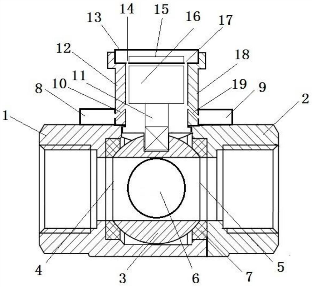
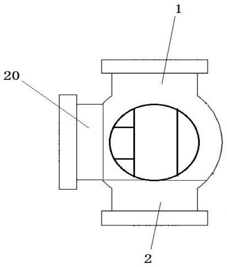
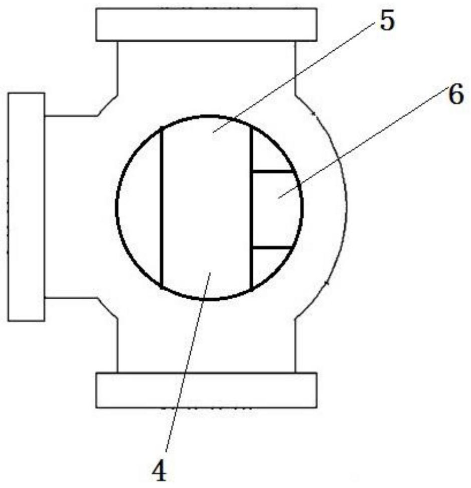
[0045]As shown: an in-vehicle control shunt device, including the first distribution valve body, a second dispensing valve body, an in-stream valve body, a spool, a seal seat, a first sensing module, a second sensing module, a drive shaft, Substrate, electrical box, control panel, motor; wherein the spool includes a first distribution channel, a second distribution channel, an incoming channel, a half-valve core, a semi-valve core, an insertion ring, a lower ring, a counter surface , Middle chamber, in-flow single-direction valve, allocated single-way valve, allocate a single-way valve two, upper positioning plate, and lower positioning plate; the strip is provided with an inclined aperture, and the lower wall of the electrical box is two segments. hole;
[0046] The fluid enters the splitter from the incoming valve body, and is exported by the first dispensing valve body, the second distribution valve body, the spool disposed inside the three parts, the valve core in the seal sea...
PUM
Abstract
Vehicle-mounted management and control flow dividing equipment comprises a first distribution valve body, a second distribution valve body, an inflow valve body, a valve element, a sealing seat, a first sensing module, a second sensing module, a transmission shaft, battens, an electrical box, a control panel and a motor. The valve element comprises a first distribution channel, a second distribution channel, an inflow channel, a first half valve element, a second half valve element, an upper embedding ring, a lower embedding ring, a butt joint face, a middle cavity, an inflow one-way valve, a first distribution one-way valve, a second distribution one-way valve, an upper positioning plate and a lower positioning plate. Inclined first hole sections are formed in the battens, and a second hole section is formed in the lower wall of the electrical box.
Description
Technical field [0001] The present invention relates to a military controlled vehicle equipment and an electronic chip field (international classification number H01), which specifically involves a car control shunt device. Background technique [0002] The main task of centralized controlled equipment is to centrally manage the various states, information, etc. of public platform equipment, real-time monitoring, controlled objects, including automotive chassis, information calendar, electric lifting rod, fuel heater, inverted mechanism, Air conditioning, generator set, power wall box, integrated power supply, etc. At present, especially in the military field, including localization of electronic components such as chips, autonomous controlled requirements are more stringent, and the core circuit boards or their core electronic components used in centralized controlled equipment are basically foreign brands. It is difficult to meet the requirements of localization. The present in...
Claims
Application Information
Patent Timeline
Application Date:The date an application was filed.
Publication Date:The date a patent or application was officially published.
First Publication Date:The earliest publication date of a patent with the same application number.
Issue Date:Publication date of the patent grant document.
PCT Entry Date:The Entry date of PCT National Phase.
Estimated Expiry Date:The statutory expiry date of a patent right according to the Patent Law, and it is the longest term of protection that the patent right can achieve without the termination of the patent right due to other reasons(Term extension factor has been taken into account ).
Invalid Date:Actual expiry date is based on effective date or publication date of legal transaction data of invalid patent.