
Gas electromagnetic valve

A gas solenoid valve and valve seat technology, applied in the field of solenoid valves, can solve the problems of slow response, inconvenient, difficult coil disassembly, etc., to achieve the effect of ensuring installation stability, reducing disassembly difficulty, and quick installation

Active Publication Date: 2021-10-01
NINGBO AOKAI COMBUSTION GAS APPLIANCE
View PDF6 Cites 0 Cited by
  • Summary
  • Abstract
  • Description
  • Claims
  • Application Information

AI Technical Summary

Problems solved by technology

[0004] (1) When the conventional solenoid valve is in use, due to its slow response speed, it cannot be closed quickly (the time to turn off the air source is greater than 25s), so in order to improve the suction Combined speed, the existing solenoid valves often use a double-coil structure, but the double-coil structure is prone to the problems of winding four terminals and inconvenient installation;
[0005](2) In the existing electromagnetic valve, when the coil and the moving iron core are attracted or disconnected, the moving iron core will contact with the static iron core or the valve cover. The side wall produces an impact, so in order to ensure a reliable connection between the valve cover and the valve seat, the holding force between the valve cover and the valve seat must be greater than 150N, which makes it difficult to disassemble the solenoid valve during maintenance;
[0006](3) The fixing of the coil in the existing solenoid valve is achieved by welding or bonding the coil and the valve seat, which not only leads to the installation of the coil The process is more difficult, and the disassembly of the coil is also more difficult when the solenoid valve is repaired and disassembled.

Method used


Image

  • Gas electromagnetic valve
  • Gas electromagnetic valve
  • Gas electromagnetic valve

Examples


Embodiment Construction

[0041] Next, in connection with the specific embodiment, it is further described in connection with the present application, and it is necessary to explain that a new embodiment may be formed in any combination between the various embodiments described below, or each of the technical features.

[0042] In the description of this application, it is to be described, for orientation, if known in the terms "center", "horizontal", "longitudinal", "length", "width", "thickness", "upper", "under" "Front", "post", "left", "right", "horizontal", "top", "bottom", "inside", "external", "counterclockwise "The etiquette orientation is based on the orientation or positional relationship shown in the drawings, which is only to facilitate the description of the present application and simplified description, rather than indicating or implying that the device or element must have a specific orientation. Construct and operation, it is not understood to limit the specific scope of protection of the ...


PUM


Abstract

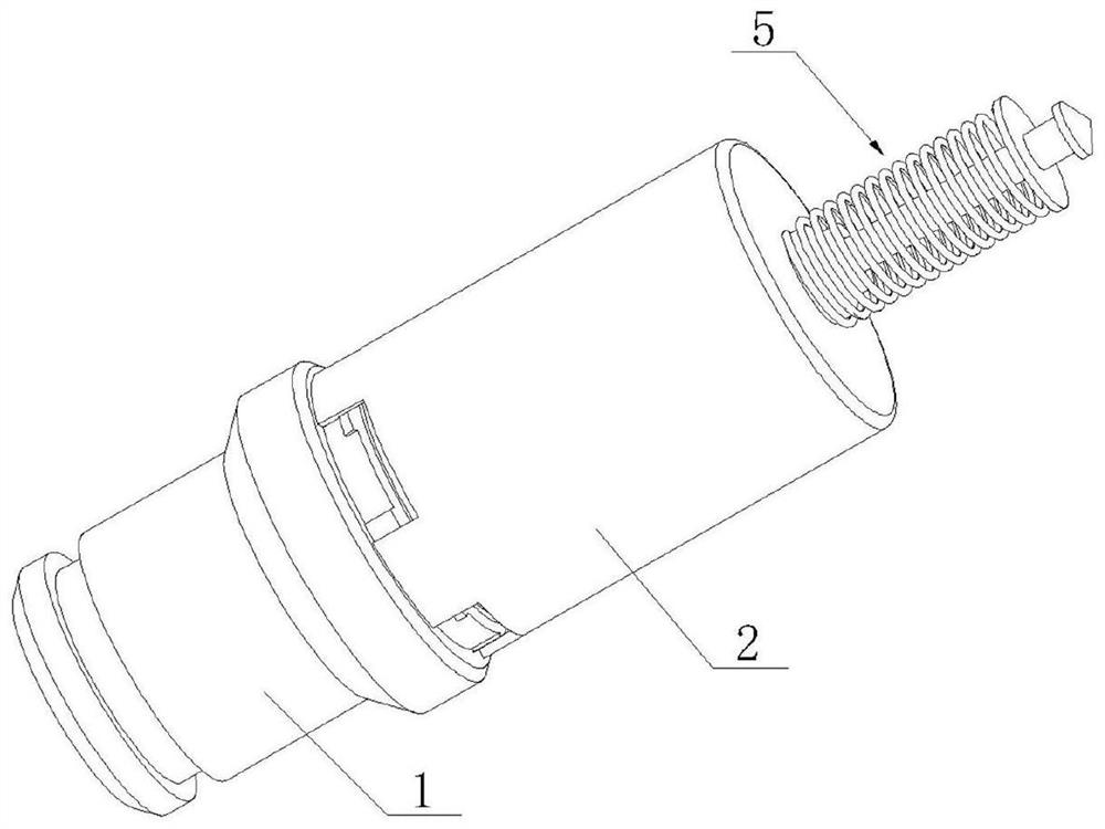
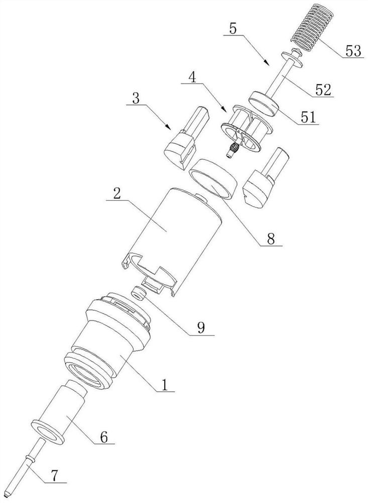
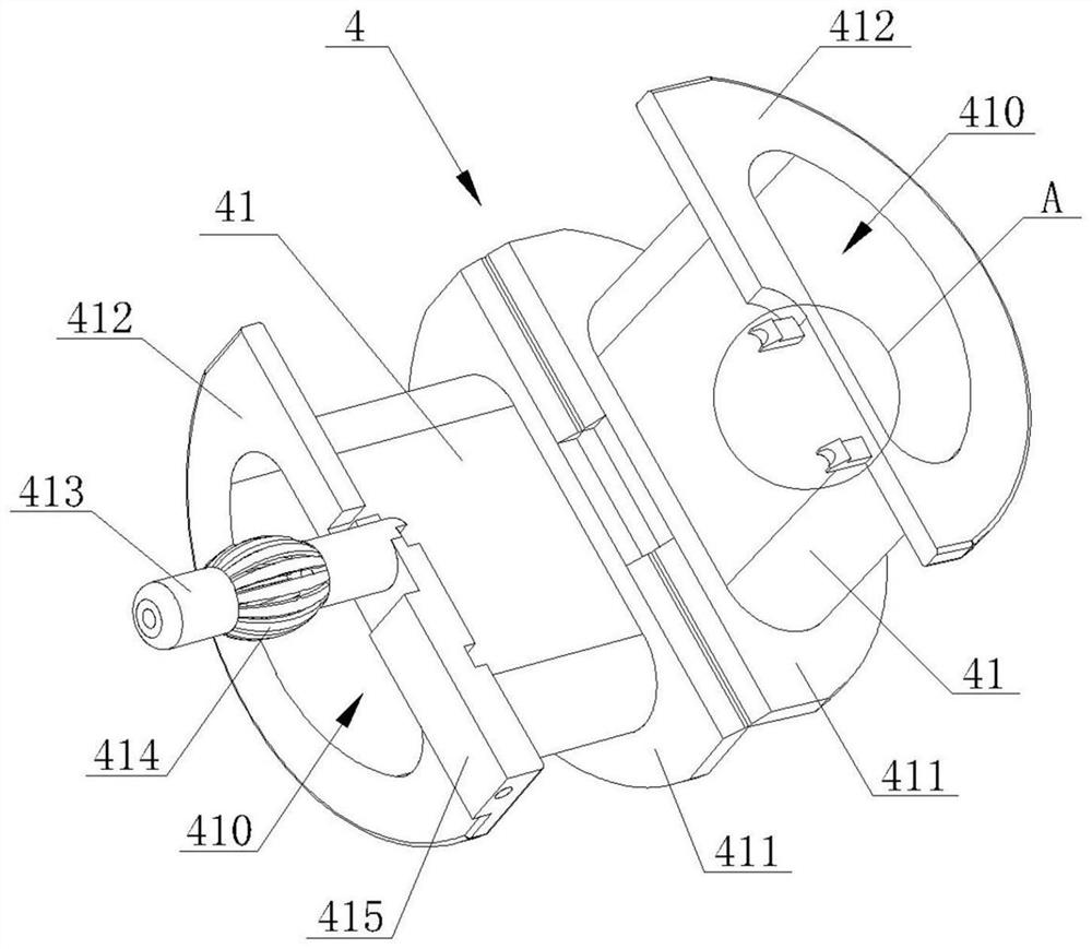
The invention discloses a gas electromagnetic valve. The gas electromagnetic valve comprises a valve seat, a coil assembly, an iron core assembly and a valve cover, the iron core assembly is installed in an installation groove in the front end of the valve seat, the coil assembly is connected to the iron core assembly in a sleeving mode and matched with the iron core assembly in a limiting mode, the valve cover is matched with a plurality of limiting grooves formed in the side wall of the front end of the valve seat through a plurality of clamping hooks arranged at the rear end, the valve cover is connected with the valve seat, meanwhile, the valve cover extrudes the iron core assembly through a pressing block, when the valve cover needs to be separated from the valve seat, the valve seat or the valve cover is rotated, and separation of the clamping hooks and the limiting grooves can be achieved. The gas electromagnetic valve has the beneficial effects that the coil assembly in double-framework flexible connection can reduce the number of wiring terminals and is convenient to install at the same time; the clamping hooks are matched with inclined faces on the two sides of the limiting grooves, so that the valve cover and the valve seat are detached by rotating the valve seat or the valve cover; and the iron core assembly of a double-mounting-seat combined structure facilitates the follow-up disassembly of the coil assembly while facilitating the limiting of the coil assembly.

Description

Technical field [0001] The present application relates to the field of the solenoid valve, particularly to a gas solenoid valve. Background technique [0002] Conventional gas cooker flame protection, there are three main methods: thermal, thermal and photoelectric wherein thermoelectric simple structure, easy installation, and the most widely used low cost. The thermoelectric flame failure mode mainly thermocouple heat sensor of the solenoid valve is driven off the gas source. [0003] Solenoid valve current thermoelectric flame failure protection configuration, there are still the following problems: [0004] (1) a conventional solenoid valve in use, because of its slow reaction rate, can not be quickly energized (off the air supply time is greater than 25S), so in order to increase the pull rate, conventional solenoid valves tend to use a double coil structure, However, the double coil structure wound prone four terminals and inconvenient installation; [0005] (2) During the ...

Claims


Application Information

Patent Timeline
IPC IPC(8): F16K31/06F16K27/08
CPCF16K31/0675F16K27/08
Inventor 李文庆林开良
Owner NINGBO AOKAI COMBUSTION GAS APPLIANCE
Learn More