Real-time control system and method for guaranteeing heat output of solid heat storage and supply system

A technology of real-time control system and heating system, applied in the direction of heating system, heating fuel, heating method, etc. Thermal effects and other issues, to achieve the effect of reducing operation steps, reducing time lag, and reducing costs

Inactive Publication Date: 2021-10-01
HEBEI INSTITUTE OF ARCHITECTURE AND CIVIL ENGINEERING
View PDF3 Cites 2 Cited by
  • Summary
  • Abstract
  • Description
  • Claims
  • Application Information

AI Technical Summary

Problems solved by technology

[0003] However, due to the heat storage and release characteristics of the heat storage body, as the heat supply time increases in a day, the heat stored in the heat storage body will gradually decrease, and the outlet air temperature will also decrease accordingly; If the air temperature is not stable, it will lead to fluctuations in the temperature of the water supply on the secondary side, which will seriously affect the heating effect
[0004] In actual engineering, the staff usually adjust the frequency of the fan or water pump based on the experience of the water supply or return water temperature. On the one hand, the accuracy is poor and it is easy to cause energy waste; on the other hand, only by observing the feedback temperature of the supply water or return water Adjustment, so that there is a time lag in the completion of temperature regulation of the heating system, which affects the heating effect of the heating system

Method used


Image

  • Real-time control system and method for guaranteeing heat output of solid heat storage and supply system
  • Real-time control system and method for guaranteeing heat output of solid heat storage and supply system

Examples


Embodiment Construction

[0042] Below, the present invention is described in detail with reference to accompanying drawing and embodiment:

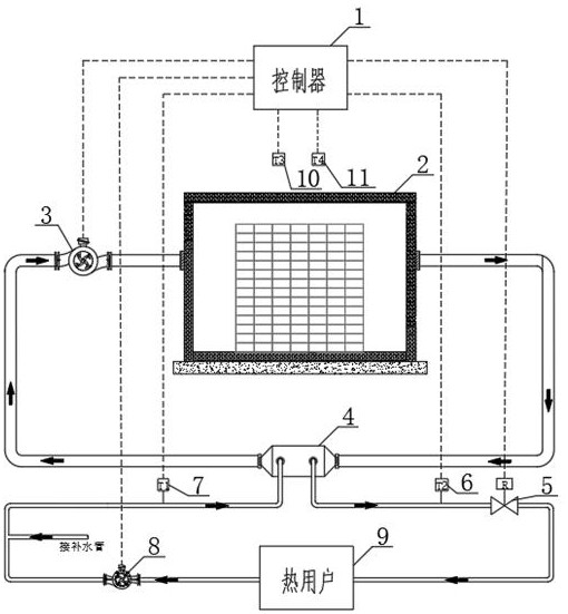
[0043] Such as Figure 1~2 As shown, a real-time control system to ensure the heat supply of the solid heat storage heat supply system includes a heat storage body 1 and a heat exchanger 4, and the air inlet and outlet sides of the heat storage body 1 and heat exchanger 4 pass through the air duct The heat exchanger 4 is connected with the heat user 9 through a water pipe, the air inlet side of the heat storage body 1 is provided with a fan 3, and the water supply side of the heat exchanger 4 is provided with a water supply pipe temperature sensor 6 , a heat meter 5, the return water side of the heat exchanger 4 is provided with a return pipe temperature sensor 7, and the water supply pipe temperature sensor 6, the heat meter 5, the return pipe temperature sensor 7, and the fan 3 are all connected to the controller 1 middle.

[0044] The temperature collection ...


PUM


Abstract

The invention discloses a real-time control system and method for guaranteeing the heat output of a solid heat storage and supply system. The control system comprises a heat storage body and a heat exchanger, the air inlet and outlet sides of the heat storage body and the heat exchanger are communicated through an air pipeline, the heat exchanger is communicated with a heat consumer through a water pipeline, a fan is arranged on the air inlet side of the heat storage body, a water supply pipe temperature sensor and a heat meter are arranged on the water supply side of the heat exchanger, and a water return pipe temperature sensor is arranged on the water return side of the heat exchanger. The method comprises the following steps of reading indoor and outdoor real-time temperature of heating, calculating indoor and outdoor temperature difference, calculating an adjusting coefficient, calculating required water supply temperature, adjusting primary side air supply quantity, judging whether actual water supply temperature meets requirements or not, and collecting operation data. The heating heat load is intelligently regulated and controlled in real time according to the indoor and outdoor temperatures of the heating room, the heating requirement of a user is guaranteed, the constant indoor temperature in the heating room is guaranteed, energy is saved to the maximum extent, resource waste is reduced, and the operation cost is reduced.

Description

technical field [0001] The invention belongs to the technical field of heat supply control, and in particular relates to a real-time control system and method for ensuring the heat supply of a solid heat storage heat supply system. Background technique [0002] The electrothermal solid energy storage heating system uses the principle of different electricity prices during peak and valley periods, stores heat during valley power periods, and converts electrical energy into heat energy; heat is released during peak power periods, and uses fans to blow heat and heat storage bodies to exchange heat with high-temperature wind and The low-temperature water of the heat exchanger performs heat exchange to achieve the purpose of heating. [0003] However, due to the heat storage and release characteristics of the heat storage body, as the heat supply time increases in a day, the heat stored in the heat storage body will gradually decrease, and the outlet air temperature will also dec...

Claims


Application Information

Patent Timeline
Patent Type & Authority Applications(China)
IPC IPC(8): F24D19/10F24D11/00
CPCF24D19/1096F24D11/002F24D2200/08F24D2220/042F24D2220/2036F24D2220/10
Inventor 孙勇牛金花许慧萱刘洋刘帅帅刘聪聪王硕
Owner HEBEI INSTITUTE OF ARCHITECTURE AND CIVIL ENGINEERING
Why Eureka
Try Eureka