Displacement heat exchanger

A heat exchanger, volumetric technology, used in indirect heat exchangers, heat exchanger types, heat exchanger shells, etc.

Active Publication Date: 2021-10-01
BAODING FUHAN THERMAL EQUIP MFG
View PDF4 Cites 0 Cited by
  • Summary
  • Abstract
  • Description
  • Claims
  • Application Information

AI Technical Summary

Problems solved by technology

[0004] The invention proposes a volumetric heat exchanger, which solves the problem of maintaining the temperature stability of the flue gas before entering the SCR reactor in the related art

Method used


Image

  • Displacement heat exchanger
  • Displacement heat exchanger
  • Displacement heat exchanger

Examples


Embodiment Construction

[0050] The technical solutions in the embodiments of the present invention will be clearly and completely described below in conjunction with the embodiments of the present invention. Apparently, the described embodiments are only some of the embodiments of the present invention, not all of them. Based on the embodiments of the present invention, all other embodiments obtained by persons of ordinary skill in the art without making creative efforts all involve the protection scope of the present invention.

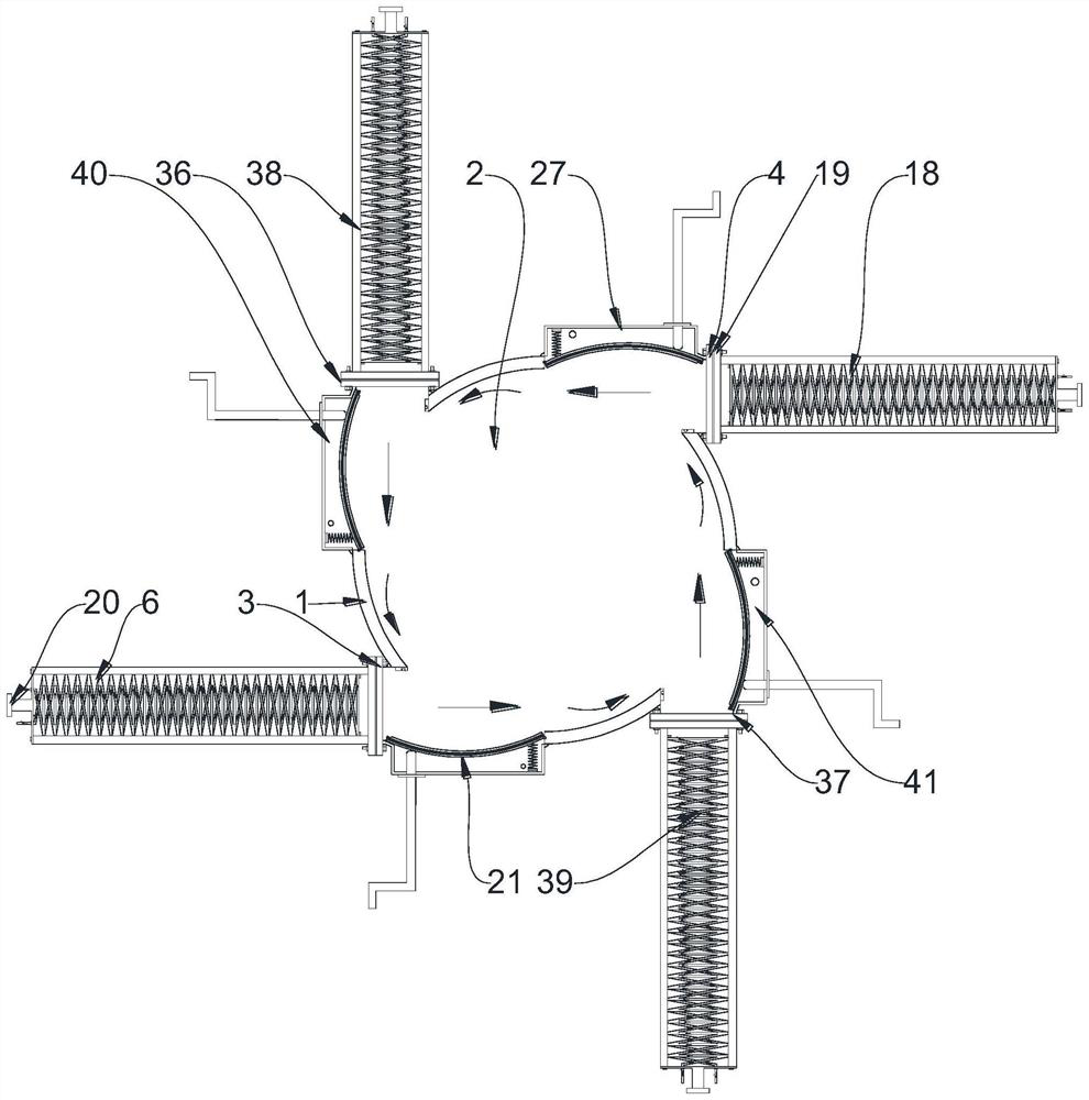
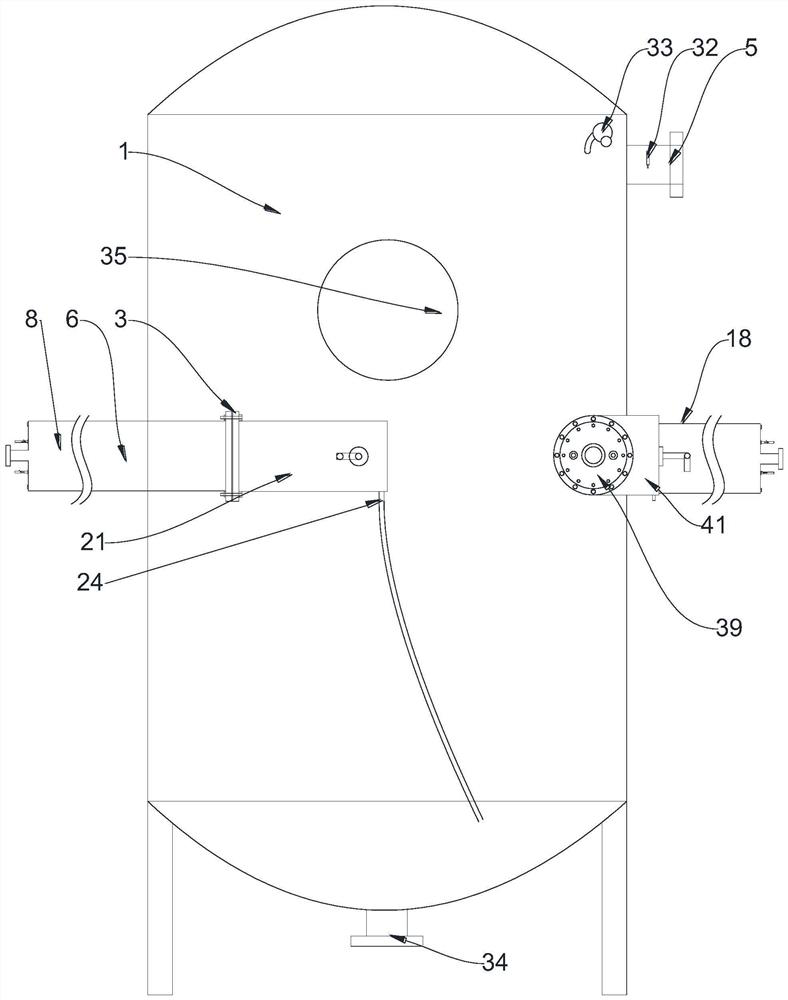
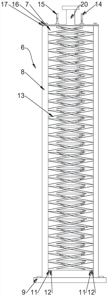
[0051] like Figure 1 to Figure 6 As shown, this example proposes

[0052] A volumetric heat exchanger comprising

[0053] tank body 1, having a first cavity 2 and a first outlet 5,

[0054] The first heating mechanism 6 and the second heating mechanism 18 having the same structure, the first heating mechanism 6 and the second heating mechanism 18 are evenly arranged tangentially along the tank body 1, and both have a second cavity 7, and the second cavity 7 communicatin...


PUM


Abstract

The invention relates to the technical field of heat exchangers, and provides a displacement heat exchanger which comprises a tank body, a first heating mechanism and a second heating mechanism, wherein the tank body is provided with a first cavity and a first outlet; the first heating mechanism and the second heating mechanism are of the same structure, are evenly arranged in the circumferential tangential direction of the tank body and are each provided with a second cavity; the second cavities and the first cavity are communicated and each comprise a main body arranged on the tank body; a blocking piece is arranged in the first cavity; a heating coil is arranged in each second cavity, abuts against the blocking piece and provided with a second inlet and a second outlet; a first baffle plate is arranged at an inlet of each second cavity through a fastener and provided with a first inlet; and each second inlet and each second outlet penetrate through each first baffle plate. By means of the technical scheme, the problem that in the prior art, the temperature of flue gas is kept stable before the flue gas enters a selective catalytic reduction (SCR) reactor is solved.

Description

technical field [0001] The invention relates to the technical field of heat exchangers, in particular to a volumetric heat exchanger. Background technique [0002] In the lime kiln desulfurization and dust removal system, before the flue gas enters the bag filter, the heat exchanger is required to perform heat exchange and cooling down to 200°C. The gas temperature after wet desulfurization is only 50-70°C. Before entering the SCR reactor It is also necessary to raise the temperature to 200°C through a heat exchanger. It has been verified that only when it is kept at this temperature before entering the SCR reactor, will it be conducive to the catalytic reaction. How to ensure that the temperature after passing through the heat exchanger can be maintained in the temperature range of 200-220° C. is a difficult problem in this field. [0003] The heat exchange effect of the existing heat exchanger is poor. The volumetric heat exchanger is a heat exchanger that uses cold and ...

Claims


Application Information

Patent Timeline
Patent Type & Authority Applications(China)
IPC IPC(8): F28D7/02F28F9/26
CPCF28D7/024F28F9/26
Inventor 张维
Owner BAODING FUHAN THERMAL EQUIP MFG
Why Eureka
Try Eureka