
Fuse wide beam forming method and system based on forward detection beam width index

A beam width and wide beam technology, applied in the field of integrated guidance fuze, can solve problems such as target damage, difficulty in piloting coordination, and insufficient response of the piloting system, so as to ensure continuous detection and tracking, increase the probability of killing, and increase the probability of activation Effect

Active Publication Date: 2021-10-01
SHANGHAI INST OF ELECTROMECHANICAL ENG
View PDF8 Cites 0 Cited by
  • Summary
  • Abstract
  • Description
  • Claims
  • Application Information

AI Technical Summary

Problems solved by technology

When the relative speed is high (such as the relative speed is greater than 5000m / s), the narrow beam tracking method requires a high beam tracking rate (for example, a beam tracking rate of at least 150° / s is required when the relative speed is 5000m / s), according to the current technology hard to accomplish
If the wide beam assignment method is used, it is necessary to set a reasonable forward detection beam width of the fuze; the detection beam width is too small to ensure that the target is always within the range of the fuze detection beam under the given rendezvous conditions, and the fuze may fail to detect the target Phenomenon: The design of the detection beam width is too large, and the operating distance cannot be increased. There may be problems such as the lack of response of the triggering system and difficulties in the coordination of the triggering, and the phenomenon that it cannot cause effective damage to the target.
[0003] According to domestic and foreign literature review, there are very few studies on the calculation of forward sounding beam width

Method used


Image

  • Fuse wide beam forming method and system based on forward detection beam width index
  • Fuse wide beam forming method and system based on forward detection beam width index
  • Fuse wide beam forming method and system based on forward detection beam width index

Examples


Embodiment 1

[0056] The present invention proposes a fast calculation method for the forward detection beam width, which is used to calculate the beam width of the guidance integrated fuze in the forward detection wide beam forming process, and solves the problem of detection and tracking of ultra-high-speed targets by the large rendezvous angle attack situational fuze. Thereby increasing the probability of missile kill.

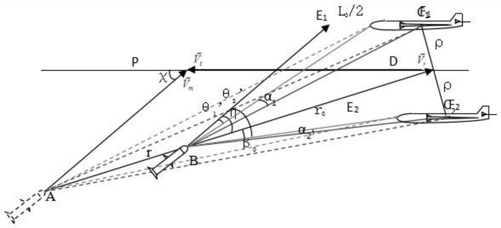
[0057] According to a method of fuze wide beamforming based on the forward detection beam width index provided by the present invention, such as figure 1 shown, including:

[0058] Step S1: Under the preset intersection conditions, through the analysis of the relative position and angular geometry of the projectile in the encounter section, establish a mathematical model of the boundary of the forward detection beam;

[0059] Step S2: Analyze the change trend of the boundary of the forward detection beam, and obtain the intersection condition corresponding to the maximu...

Embodiment 2

[0103] Embodiment 2 is a preferred example of embodiment 1

[0104] The fast calculation method of the forward sounding beam width proposed by the present invention comprises the following steps:

[0105] (1) Under the given rendezvous conditions, the mathematical model formula of the forward detection beam boundary is deduced through the analysis of the relative position and angular geometric relationship of the projectile in the encounter section;

[0106] (2) Analyze the trend of forward detection beam boundary with missile speed, target speed, rendezvous angle, detection distance, miss distance, missile angle of attack, angle pointing error, target geometric size, data processing time, etc., and find out its maximum value;

[0107] (3) The calculated maximum value of the forward detection beam boundary is used as the value of the forward detection beam width, and the forward wide beamforming design of the integrated guidance fuze is carried out.

[0108] The mathematical ...

Embodiment 3

[0112] Embodiment 3 is a preferred example of embodiment 1 and / or embodiment 2

[0113] The present invention provides a method for fuze wide beamforming based on the forward detection beam width index, including:

[0114] Step 1: Determine the missile velocity vector modulus when the missile-target encounters Target velocity vector modulus Rendezvous angle χ, detection distance r, miss amount ρ, missile attack angle γ m , Angle pointing error Δθ, target geometric size L 0 , data processing time t 0 Values, such as missile speed 1000m / s~2000m / s, target speed 1000m / s~3000m / s, rendezvous angle 0°~20°, detection range 200m~300m, miss distance 0m~8m, missile attack angle 0°~ 5°, angle pointing error maximum 2°, target geometric size 8m~25m, data processing time maximum 2ms.

[0115] Step 2: Deduce the mathematical model formula of the forward sounding beam boundary:

[0116] θ 0 =max(2θ 10 ,2θ 20 )

[0117] In the formula:

[0118] θ 10 = θ 1 '+γ m +Δθ

[0119] θ ...


PUM


Abstract

The invention provides a fuse wide beam forming method and system based on a forward detection beam width index. The method comprises the steps of S1, building a forward detection beam boundary mathematical model through encountering section missile and target relative position and angle geometric analysis under a preset intersection condition; S2, analyzing the forward detection beam boundary change trend to obtain a intersection condition corresponding to the maximum value of a forward detection beam boundary; S3, inputting the intersection condition corresponding to the maximum value of the forward detection beam boundary into the forward detection beam boundary mathematical model, and calculating to obtain a forward detection beam width value; and S4, according to the calculated forward detection beam width value, setting the guidance integrated fuse forward detection beam width index, completing fuse wide beam forming, and ensuring that the target head is always in a fuze forward detection beam range under a preset intersection condition.

Description

technical field [0001] The present invention relates to the technical field of integrated guidance fuze, in particular, to a method and system for forming a wide beam of a fuze based on a forward detection beam width index, and more specifically, to a fast calculation method for a forward detection beam width. Background technique [0002] The ultra-high-speed targets that appeared in the early stage had a small maneuvering force, and the anti-orbit interception method was often used when the missile was attacked. Directing the detection beam can ensure the continuous detection and tracking of the target by the guidance integrated fuze. With the emergence of hypersonic targets with variable ballistic maneuvers, the difficulty of reverse orbit interception has been greatly increased, and larger rendezvous angles and larger missile attack angles will appear in the missile-target encounter segment. Under the conditions of high relative speed, large rendezvous angle, and large ...

Claims


Application Information

Patent Timeline
Patent Type & Authority Applications(China)
IPC IPC(8): F41G7/22F42B15/01H04B7/06G06F30/20
CPCF41G7/22F41G7/2273F42B15/01H04B7/0617G06F30/20
Inventor 金桂玉史志中蔡克荣迟德建朱志鹏
Owner SHANGHAI INST OF ELECTROMECHANICAL ENG
Learn More