Disturbing force suppression method for two-degree-of-freedom electro-hydraulic vibration table

An electro-hydraulic vibration and degree of freedom technology, applied in vibration testing, machine/structural component testing, measuring devices, etc., can solve problems such as affecting the control accuracy of the shaking table system and reducing the control accuracy of the two-degree-of-freedom electro-hydraulic shaking table system. , to achieve the effect of improving the control accuracy

Active Publication Date: 2021-10-01
DALIAN MARITIME UNIVERSITY
View PDF5 Cites 0 Cited by
  • Summary
  • Abstract
  • Description
  • Claims
  • Application Information

AI Technical Summary

Problems solved by technology

Affected by interference factors such as foundation elasticity and flexible connection, the control accuracy of the two-degree-of-freedom electro-hydraulic vibration table system is greatly reduced
Taking the movement of the electro-hydraulic vibration table along the roll degree of freedom as an example, the analysis shows that when the traditional control method is adopted, the time-domain peak error between the acceleration output signal of the roll degree of freedom and the acceleration reference signal is about 60%, which seriously affects the stability of the vibration table. System Control Accuracy

Method used


Image

  • Disturbing force suppression method for two-degree-of-freedom electro-hydraulic vibration table
  • Disturbing force suppression method for two-degree-of-freedom electro-hydraulic vibration table
  • Disturbing force suppression method for two-degree-of-freedom electro-hydraulic vibration table

Examples


Embodiment Construction

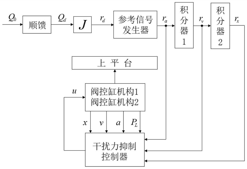
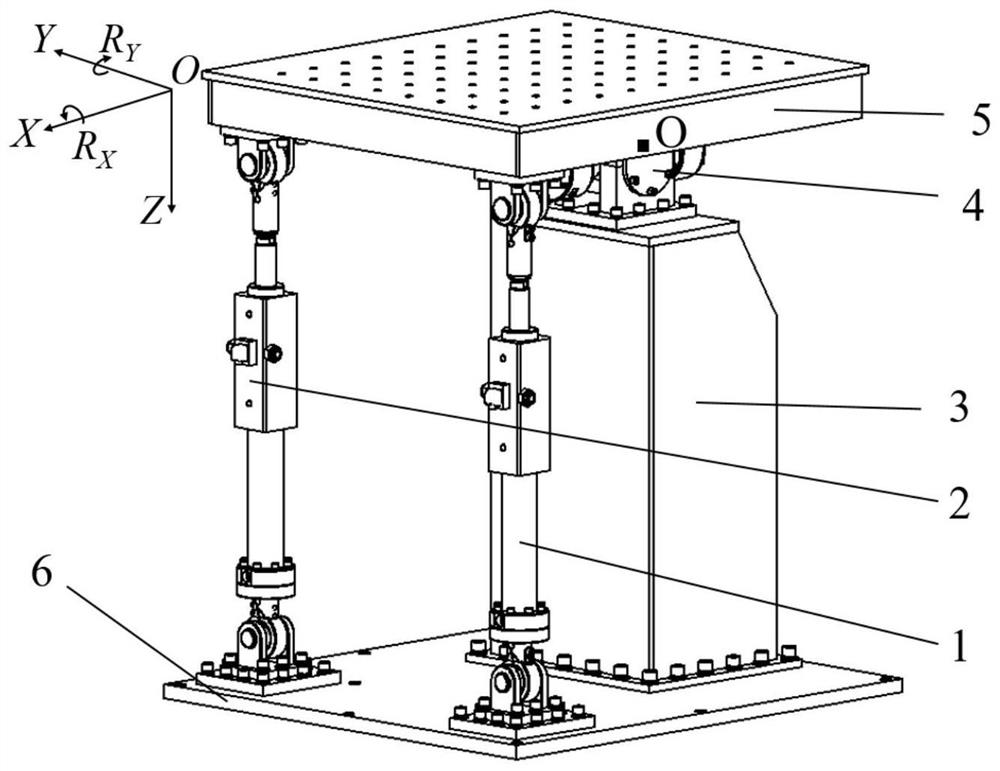
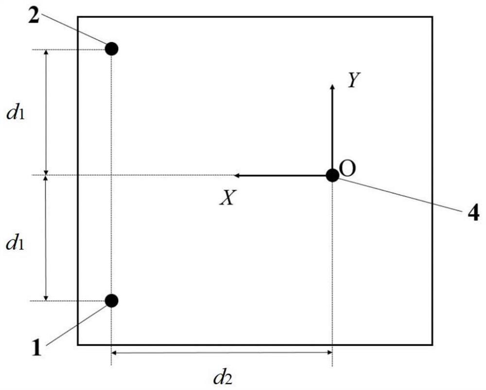
[0044] The present invention will be further described below in conjunction with the accompanying drawings. Such as Figure 1-3As shown, a method for suppressing interference force of a two-degree-of-freedom electro-hydraulic vibration table, the two-degree-of-freedom electro-hydraulic vibration table includes two vertical valve control cylinder mechanisms, a large Hooke hinge 4, a support 3, and an upper platform 5 and lower platform 6; the two vertical valve-controlled cylinder mechanisms are No. 1 valve-controlled cylinder mechanism 1 and No. 2 valve-controlled cylinder mechanism 2; the No. 1 valve-controlled cylinder mechanism 1 and No. 2 valve-controlled cylinder mechanism The lower end of the cylinder mechanism 2 is connected to the lower platform 6 through respective ball joints, and the upper end is connected to the upper platform 5 through respective ball joints respectively, and the upper platform 5 is connected to the support 3 through a large Hooke hinge 4. The lo...


PUM


Abstract

The invention discloses a disturbing force suppression method for a two-degree-of-freedom electro-hydraulic vibration table. The disturbing force suppression method comprises the following steps that a two-degree-of-freedom acceleration reference signal is left multiplied by a matrix J and then serves as an input signal of a reference signal generator module; an output signal ra is obtained through the reference signal generator module; the ra is used as an input signal of an integrator 1 module, and an output signal rv is obtained; the rv is used as an input signal of an integrator 2 module, and an output signal rx is obtained; a displacement signal x, a speed signal v and an acceleration signal a of a hydraulic cylinder piston rod of each valve control cylinder mechanism and a pressure difference signal PL of two cavities of a hydraulic cylinder are collected; the signals rx, rv, ra, x, v, a and PL serve as input signals of a disturbing force suppression controller module, and an output signal u of the disturbing force suppression controller module is calculated; and an output signal u of the disturbing force suppression controller module serves as a driving signal of the two valve-controlled cylinder mechanisms and is input into the two valve-controlled cylinder mechanisms to drive the two-degree-of-freedom electro-hydraulic vibration table to move. According to the invention, the control precision of the two-degree-of-freedom electro-hydraulic vibration table is obviously improved.

Description

technical field [0001] The invention relates to a two-degree-of-freedom electro-hydraulic vibration table, in particular to a method for suppressing interference force of a two-degree-of-freedom electro-hydraulic vibration table. Background technique [0002] The multi-degree-of-freedom electro-hydraulic vibration table is the key equipment for simulating the vibration environment of large-scale structures or equipment. By reproducing the acceleration signal measured in the environment, the anti-vibration performance of the structure or equipment in the vibration environment is assessed. It is widely used in aerospace, bridge construction, ships, etc. , vehicles and other fields. The control system is the core technology of the electro-hydraulic vibration table. [0003] The two-degree-of-freedom electro-hydraulic vibration table is driven by two sets of valve-controlled cylinder mechanisms, and has two degrees of freedom of motion, roll and pitch. The controller design of...

Claims


Application Information

Patent Timeline
Patent Type & Authority Applications(China)
IPC IPC(8): G01M7/06G01M7/02
CPCG01M7/06G01M7/022
Inventor 关广丰范大莽熊伟王海涛马文琦
Owner DALIAN MARITIME UNIVERSITY
Why Eureka
Try Eureka