
Bidirectional current source circuit

A bidirectional current and source circuit technology, applied in the field of current source, can solve the problem that single-amplitude voltage signal cannot be converted into driving signal, etc.

Active Publication Date: 2021-10-01
BEIJING HANGKE ENGINE CONTROL SYST SCI & TECH +1
View PDF5 Cites 0 Cited by
  • Summary
  • Abstract
  • Description
  • Claims
  • Application Information

AI Technical Summary

Problems solved by technology

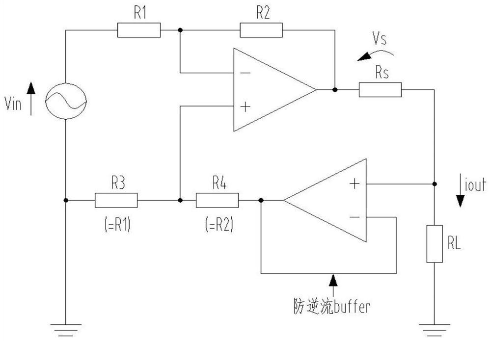
[0004] The driving signal of the electro-hydraulic servo valve and hydraulic servo motor is a bidirectional current source, and the output of the single-chip microcomputer is a single-amplitude voltage signal. However, the current existing bidirectional current source circuit, such as figure 2 As shown, it is realized by a combination of dual operational amplifiers. In this circuit, a positive and negative bidirectional voltage source needs to be used, and negative feedback is used to ensure that the voltage at both ends of the resistor Rs remains unchanged to realize a bidirectional current source. It is impossible to realize the single-amplitude voltage output by the microcontroller. The signal is converted into the driving signal required by the electro-hydraulic servo valve or hydraulic servo motor

Method used


Image

  • Bidirectional current source circuit
  • Bidirectional current source circuit
  • Bidirectional current source circuit

Examples


Embodiment approach

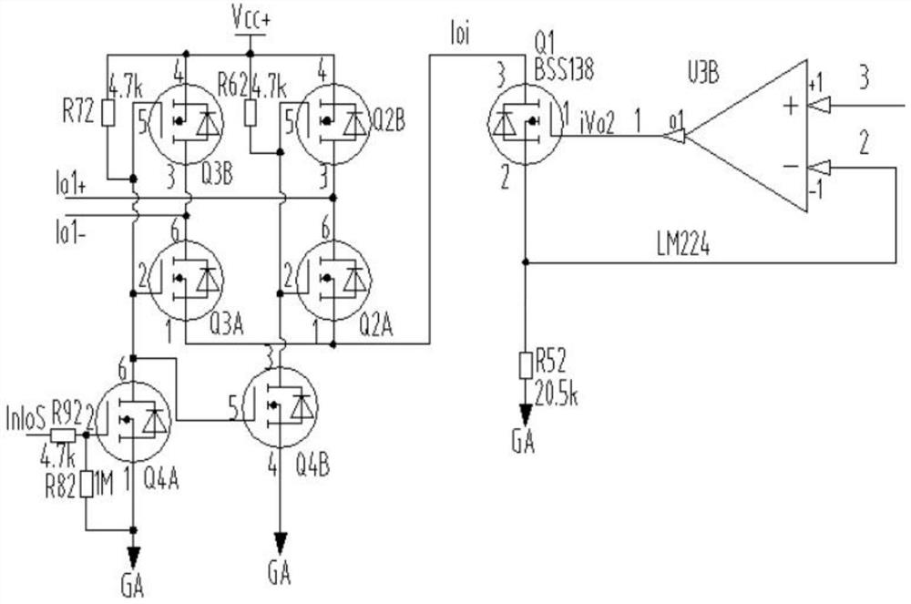
[0041] As an optional implementation manner, the second transistor bridge circuit includes:

[0042] The second PMOS transistor Q3B, the third NMOS transistor Q3A, the fourth NMOS transistor Q4A, the second resistor R72, the third resistor R82 and the fourth resistor R92, the source of the second PMOS transistor Q3B is respectively connected to the first transistor The second end of the bridge circuit is connected to one end of the second resistor R72; the gate of the second PMOS transistor Q3B is respectively connected to the other end of the second resistor R72 and the gate of the third NMOS transistor Q3A connected to the drain of the fourth NMOS transistor Q4A; the drain of the second PMOS transistor Q3B and the drain of the third NMOS transistor Q3A are the second output terminals of the bidirectional current source circuit; the third The source of the NMOS transistor Q3A is respectively connected to the first terminal of the second transistor bridge circuit and the outpu...


PUM


Abstract

The invention relates to a bidirectional current source circuit. The circuit comprises a voltage and current conversion circuit and a unidirectional and bidirectional conversion circuit which are connected in sequence; the first end of a first transistor bridge circuit in the unidirectional and bidirectional conversion circuit and the first end of a second transistor bridge circuit in the unidirectional and bidirectional conversion circuit are connected with the output end of the voltage and current conversion circuit, and the second end of the first transistor bridge circuit is connected with the second end of the second transistor bridge circuit; the fourth end of the first transistor bridge circuit and the fourth end of the second transistor bridge circuit are connected with the analog ground; the fifth end of the first transistor bridge circuit is connected with the fifth end of the second transistor bridge circuit; and the sixth end of the second transistor bridge circuit is connected with the output end of the excitation signal. According to the invention, a single-amplitude voltage signal output by the single-chip microcomputer can be converted into a bidirectional current signal.

Description

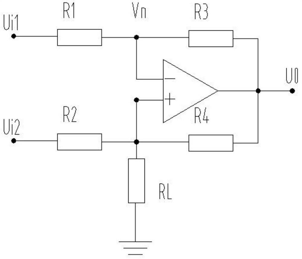
technical field [0001] The invention relates to the field of current sources, in particular to a bidirectional current source circuit. Background technique [0002] Electro-hydraulic servo valves and hydraulic servo motors are the key components in electro-hydraulic servo control. They are a kind of analog current signals that control specified physical quantities accordingly. For example, electro-hydraulic servo valves are usually used to adjust flow and pressure. Servo motors It is often used to drive shaft rotation, etc. [0003] Bidirectional current source circuit, also called Howland circuit, is also called Howland current pump circuit in the theory of active network. It is a constant current source circuit. The circuit schematic diagram is as follows: figure 1 shown. Two positive and negative feedback branches are introduced into the circuit, and the load resistance is grounded, forcing the negative feedback to be stronger than the positive feedback, ensuring that t...

Claims


Application Information

Patent Timeline
IPC IPC(8): G05F1/56
CPCG05F1/561
Inventor 付居岳袁树峥廖远洋杨蓓严菡王磊
Owner BEIJING HANGKE ENGINE CONTROL SYST SCI & TECH
Learn More