Delay-start pre-charging circuit for robot
A technology of delayed start and pre-charging circuit, applied in circuit devices, battery circuit devices, safety/protection circuits, etc., can solve problems such as battery pre-charging circuit failure, inability to pre-charge the post-driver, and inability to protect the DC contactor, etc. , to achieve the effect of reducing the starting current
- Summary
- Abstract
- Description
- Claims
- Application Information
AI Technical Summary
Problems solved by technology
Method used
Image

Examples
Embodiment
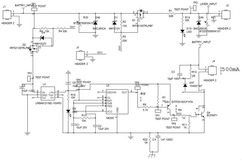
[0015] Example: Reference figure 1 The robot delay start pre-charging circuit shown in the figure includes robot battery input terminal J1, power input terminal BATTRY_INPUT, pre-charging resistance power-on switch MOS tube Q1, subsequent stage circuit charging resistor R1, and subsequent stage load connection terminal connected sequentially. J2.
[0016] In this embodiment, pin 1 of the robot battery input terminal J1 is connected to the power input terminal BATTRY_INPUT, and pin 2 is grounded.
[0017] The MOS tube Q1 of the pre-charging resistance power-on switch is a P-channel MOS tube, and its model is IRF5210STRLPBF. A resistor R2 with a resistance value of 10KΩ is connected between the gate and the source of the pre-charge resistance power-on switch MOS tube Q1, and the model is MM1Z12V The diode D1, the resistor R2 and the diode D1 are connected in parallel, the resistor R5 with a resistance value of 30K is connected between the resistor R2 and the gate of the pre-cha...
PUM
 Abstract
Description
Claims
Application Information
 - Generate Ideas
- Intellectual Property
- Life Sciences
- Materials
- Tech Scout
- Unparalleled Data Quality
- Higher Quality Content
- 60% Fewer Hallucinations
Browse by: Latest US Patents, China's latest patents, Technical Efficacy Thesaurus, Application Domain, Technology Topic, Popular Technical Reports.
© 2025 PatSnap. All rights reserved.Legal|Privacy policy|Modern Slavery Act Transparency Statement|Sitemap|About US| Contact US: help@patsnap.com