Detachable quick connecting device

A quick-connect, detachable technology, used in covering/lining, architecture, building construction, etc., to solve problems such as difficult disassembly of connecting devices

Pending Publication Date: 2021-10-08
吕秋海
View PDF0 Cites 1 Cited by
  • Summary
  • Abstract
  • Description
  • Claims
  • Application Information

AI Technical Summary

Problems solved by technology

[0003] In order to improve the problem that common connection devices are diffic

Method used


Image

  • Detachable quick connecting device
  • Detachable quick connecting device
  • Detachable quick connecting device

Examples


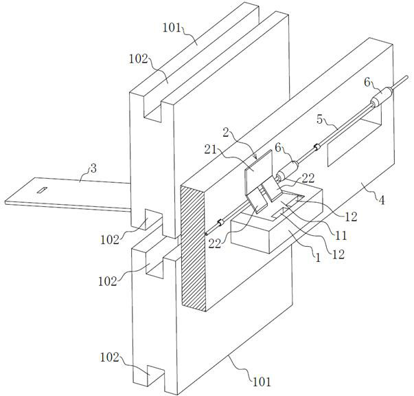
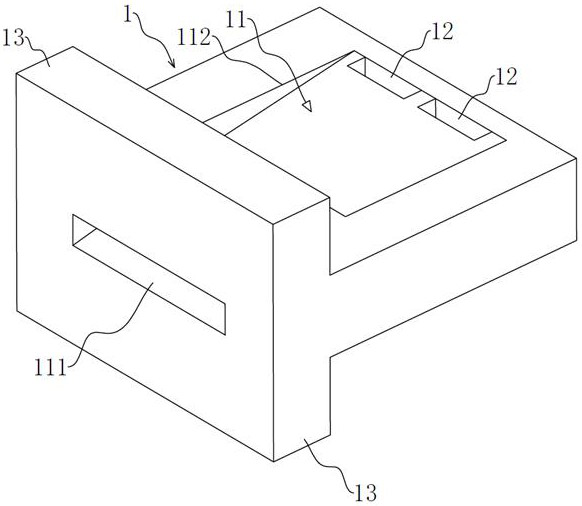
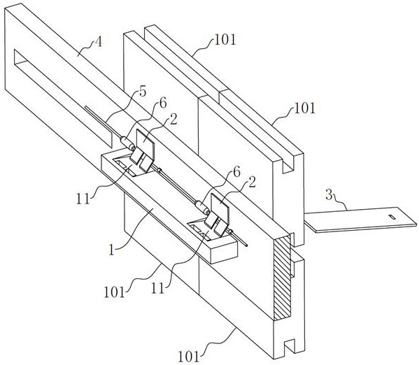
Embodiment 1 Embodiment 1 1 。 pic 1 and pic 2,1、2 and 3,2 1 4,4 Embodiment ,1 and 3、、 or ,2 or ,、,、,、, or 、、 3 。 41,14,101 and and 102,1024。101、、 other or (、、)。 1 1 11,11 no. 1 111 and no. 2 112, no. 1 11114, no. 2 11212,2 1 no. 2 11211,;3 no. 1 11111211,。 221 and 22,214,22 and 21 1 ,22, other Embodiment 22 1 or 3 or 。2,,101,22,2211。 1 no. 2 11212,1211,12 and 22,12 and 22 1 ,1,2212,1,。 other Embodiment ,12,。 22, other Embodiment 22,22, effect comparative 。 21 and 4 approach :, other Embodiment approach 、、、 or 。 approach ,21 and 4。 45,45,5,56,6,6,562211,。5 and 6, and 311, approach ,。 13,13 or , other ,1,13 and 1 1 “T”。,13 1 101,。4 and 1101,。 Embodiment 1 Embodiment :24,4、 other or ,1101102,1 and 101,11014, to 2 no. 2 11211, and 101;,3 no. 1 11111,211,;5,6 1 ,622 and 4,2211,。 1 56,5,6, 1 22,。 ,, and approach ,,;、,,,,,,,,。 Embodiment 2 Embodiment 2 1 。 pic 3, and Embodiment 1 : 1,111, 1 11 corresponding 1 101, 1 5 corresponding 6,4 corresponding 2,6 corresponding 1 2。 other Embodiment ,111 3 、 4 or 。 Embodiment 3 Embodiment 3 1 。 pic 4, and Embodiment 1 : 1 13,1,13 and 1 1 “L”。, 1 13 1 101, or 。 Embodiment no. 1 111 and no. 2 112。, other Embodiment , no. 1 111 and no. 2 112。 Embodiment 4 Embodiment 4 1 。 pic 5, and Embodiment 1 : 13,1,13 and 1 1 “Y”,13,,13 1 101,。。 Embodiment 5 Embodiment 5 1 。 pic 6, and Embodiment 1 : 13,1,13 and 1 1 “↑”,13,,13 1 101,。。 Embodiment 6

[0005] The following is attached Figure 1-7 The application is described in further detail. Embodiment 1 Embodiment 1 of the present application discloses a detachable quick connection device. refer to figure 1 and figure 2, the detachable quick connection device includes a connecting part 1, an elastic locking piece 2 and an unlocking part 3, a part of the elastic locking piece 2 is fixed on the installation main body 4, and the installation main body 4 is in the shape of a rectangular plate in this embodiment, and the connecting part 1 and the unlocking part 3 are made of metal, plastic, wood or composite material, and the elastic locking piece 2 is made of metal or composite material, and the above composite material can be a combination of metal and plastic, or a combination of plastic and wood , also can be combined by metal, wood, or the combination of metal, plastic, wood three kinds of materials all can. The installation main body 4 is provided with a hole for th...


PUM


Abstract

The invention relates to a detachable quick connecting device. The detachable quick connecting device comprises a connecting part, an elastic locking plate and an unlocking part, wherein one part of the elastic locking plate is fixed on a mounting main body; a hole for allowing the connecting part to pass through is formed in the mounting main body; the end part, extending out of the outer surface of the mounting main body, of the connecting part is equipped with a limiting structure; the bottom and/or the top of a mounted product are/is equipped with blocking slots adaptive to the limiting structure; an inclined slot is formed in the connecting part; the inclined slot comprises a first slot hole and a second slot hole; the first slot hole is positioned in the end side surface, extending out of the outer surface of the mounting main body, of the connecting part; the second slot hole is positioned in the surface, close to the elastic locking plate, of the connecting part; when the other part of the elastic locking plate extends into the inclined slot from the second slot hole and abuts against the inclined slot, the locking purpose is realized; and when the unlocking part extends into the inclined slot from the first slot hole and pushes part of the elastic locking plate out of the inclined slot, the unlocking purpose is realized. The detachable quick connecting device has the following expectable technical effects that: the structure is detachable, accessories can be dismounted and replaced freely, and a recycling rate is high.

Description

technical field [0001] The present application relates to the technical field of building installation, in particular to a detachable quick connection device. Background technique [0002] Architectural decoration involves every corner of people's lives, and the interior and exterior walls of buildings need to be decorated. There are many types of decorative surfaces used for decoration in the market, the most important of which are ceramic tiles and wooden decorative surfaces. In today's society, the concept of time is getting stronger and stronger, and the time for decoration is getting shorter and shorter. When connecting, most of them are directly connected by glue or welding. The structure of the current connection device is too simple, and most of them cannot be disassembled. Most of the fixed parts are fixed by drilling holes on the fixed surface and using glue or welding structure. The user needs to spend a lot of time and energy to connect the fixed part with the e...

Claims


Application Information

Patent Timeline
IPC IPC(8): E04F13/24E04F13/072
CPCE04F13/0832E04F13/0846E04F13/0858
Inventor 吕秋海
Owner 吕秋海
Why Eureka
Try Eureka