Adjusting type air source heat pump fan structure convenient to install
An air source heat pump, regulating technology, applied to heat pumps, components of pumping devices used for elastic fluids, pumps, etc., can solve the problems of high installation work intensity for staff, shortened working life of equipment, and potential safety hazards, etc. Achieve the effect of simple structure, reduce installation strength and reduce potential safety hazards
- Summary
- Abstract
- Description
- Claims
- Application Information
AI Technical Summary
Problems solved by technology
Method used
Image

Examples
Embodiment Construction
[0025] The following will clearly and completely describe the technical solutions in the embodiments of the present invention with reference to the accompanying drawings in the embodiments of the present invention. Obviously, the described embodiments are only some, not all, embodiments of the present invention. Based on the embodiments of the present invention, all other embodiments obtained by persons of ordinary skill in the art without making creative efforts belong to the protection scope of the present invention.
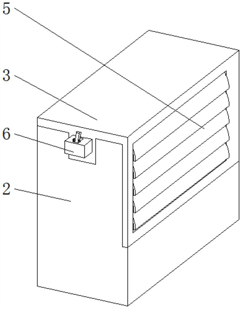
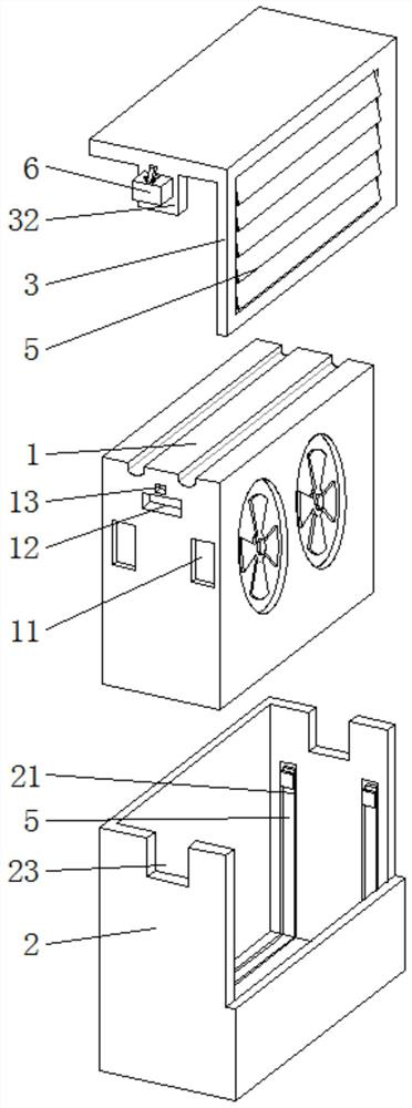
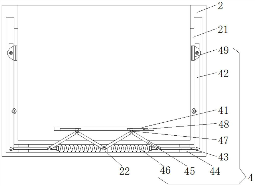
[0026] see Figure 1-3 , the present invention provides a technical solution: an adjustable air source heat pump fan structure that is easy to install, including a body base 1, an outer shell 2 and a shell cover 3, the outer shell 2 is a double-layer structure, and the inner side of the outer shell 2 There is a U-shaped notch 21, and the U-shaped notch 21 is provided with a shock-absorbing clamping mechanism 4. The shock-absorbing clamping mechanism 4 includes...
PUM
 Abstract
Description
Claims
Application Information