Laser marking equipment and automatic focusing method thereof

A laser marking equipment and automatic focusing technology, applied in typewriters, printing, etc., can solve the problems of unclear lens focal length accurate parameters, heavy workload, cumbersome operation process, etc., to eliminate human measurement errors and measurement reference point errors , reduce mechanical design errors and sensor installation errors, and achieve the effect of focusing operation

Active Publication Date: 2021-10-12
HANS LASER TECH IND GRP CO LTD
View PDF9 Cites 1 Cited by
  • Summary
  • Abstract
  • Description
  • Claims
  • Application Information

AI Technical Summary

Problems solved by technology

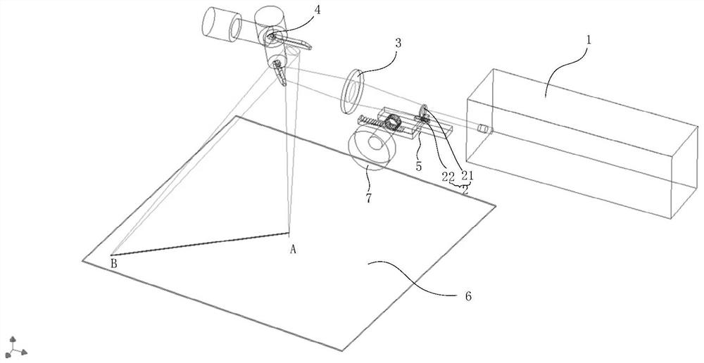
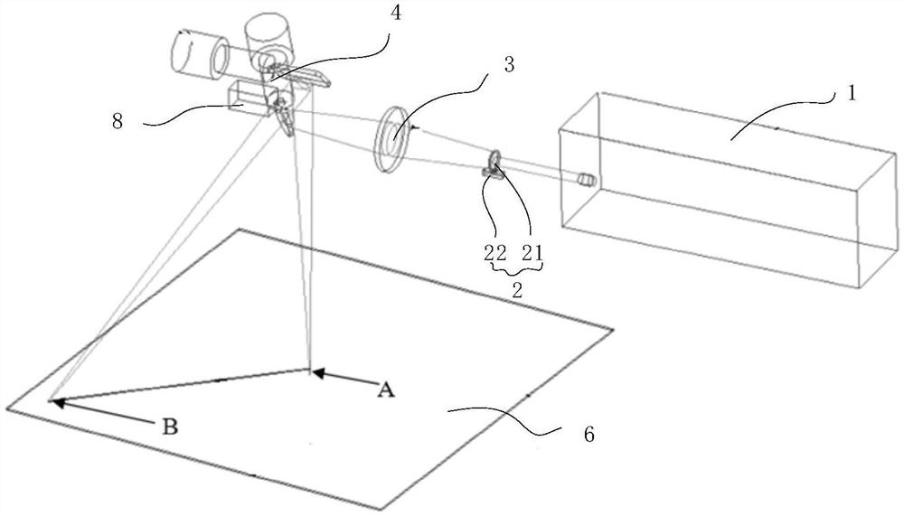
But, there is following problem in this scheme: firstly, focusing lens 21 is in figure 1 The position of the first guide rail 5 shown in the figure needs to be determined according to the focal length of the focusing lens 21 and the focusing lens 3. In view of confidentiality and other reasons, usually the debugger does not know the exact parameters of the lens focal length. The stroke of the guide rail 5 may only be based on personal experience, and the handwheel needs to be operated repeatedly; at the same time, due to the possible processing and assembly errors of the focusing lens 21 and the focusing lens 3, the actual value of the focal length of the focusing lens 21 and the focusing lens 3 may be different from the design. Values ​​are different, resulting in inaccurate calculation values; moreover, in practical applications, for different types of products, the thickness of marking objects often changes, and repeated marking and debugging are required. Not only the workload is heavy, but the operation process is cumbersome, it may also affect Focus effect

Method used


Image

  • Laser marking equipment and automatic focusing method thereof
  • Laser marking equipment and automatic focusing method thereof
  • Laser marking equipment and automatic focusing method thereof

Examples


Embodiment Construction

[0045] In order to make the technical problems, technical solutions and beneficial effects to be solved by the present invention clearer, the present invention will be further described in detail below in conjunction with the accompanying drawings and embodiments. It should be understood that the specific embodiments described here are only used to explain the present invention, not to limit the present invention.

[0046] It should be noted that when an element is referred to as being “fixed” or “disposed on” another element, it may be directly on the other element or be indirectly on the other element. When an element is referred to as being "connected to" another element, it can be directly connected to the other element or indirectly connected to the other element.

[0047] It is to be understood that the terms "length", "width", "top", "bottom", "front", "rear", "left", "right", "vertical", "horizontal", "top" , "bottom", "inner", "outer" and other indicated orientations...


PUM


Abstract

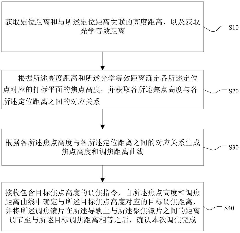
The invention provides laser marking equipment and an automatic focusing method thereof. The high-precision automatic focusing can be realized, and the method comprises the following steps that a positioning distance and a height distance associated with the positioning distance are acquired, and an optical equivalent distance is acquired; according to the height distance and the optical equivalent distance, the focus height of a marking plane corresponding to each positioning point is determined, and the corresponding relation between each focus height and each positioning distance is obtained; a focus height and focusing distance curve is generated according to the corresponding relation between each focus height and each positioning distance; and a focusing instruction containing a target focus height is received, a target focusing distance corresponding to the target focus height is determined from the focus height and focusing distance curve, and after the distance between the focusing lens on the guide rail and the focusing lens is adjusted to be equal to the target focusing distance, it is confirmed that the focusing is completed.

Description

technical field [0001] The invention belongs to the technical field of laser marking, and in particular relates to a laser marking device and an automatic focusing method of the laser marking device. Background technique [0002] Such as figure 1 As shown, when the laser marking equipment marks the marking positions A and B on the marking plane, the ideal laser focus has the only and the thinnest focus point, that is, the focus position. When marking point A and point B respectively, the focal length corresponding to the laser focus of the two marking positions will change. At this time, if the marking position is switched, the focus height will not change accordingly; When the marking object of a certain thickness is adjusted to the focus position for marking, if the marking object of other thickness is replaced and the original focus height remains unchanged, the point where the laser beam hits the marking plane will not be ideal. Focus point, which will lead to problems...

Claims


Application Information

Patent Timeline
Patent Type & Authority Applications(China)
IPC IPC(8): B41J2/47B41J3/407B41J3/44
CPCB41J2/471B41J3/407B41J3/4073B41J3/445
Inventor 陈略刘宁冯磊任宁高云峰
Owner HANS LASER TECH IND GRP CO LTD
Why Eureka
Try Eureka