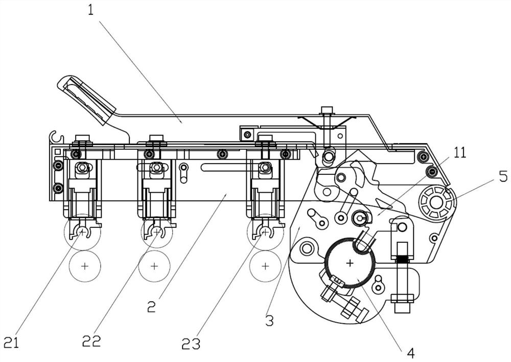
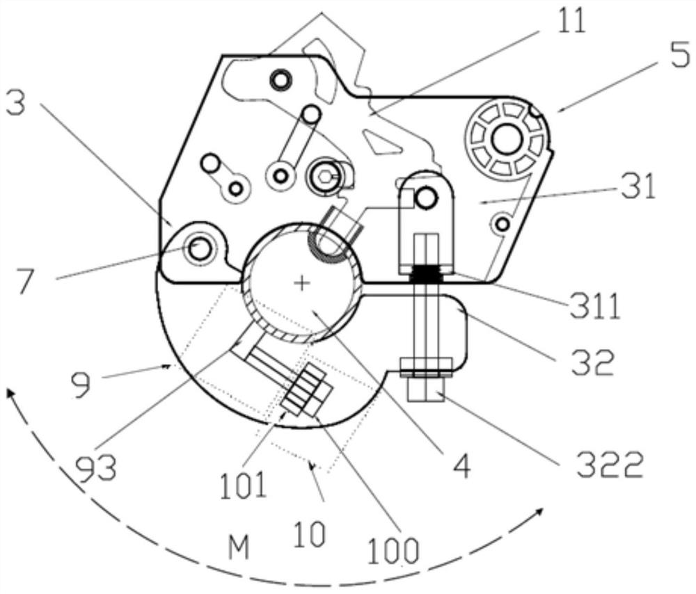
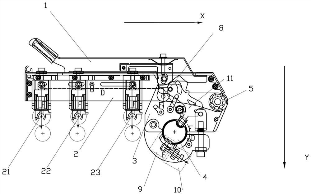
Spinning machine cradle and pressure fine adjustment method

A technology for spinning machines and cradles, which is applied to spinning machines, textiles, papermaking, and drafting equipment. The effect of simple structure

Pending Publication Date: 2021-10-12
ZHANGJIAGANG GUANGDA TEXTILE MACHINERY
View PDF0 Cites 0 Cited by
  • Summary
  • Abstract
  • Description
  • Claims
  • Application Information

AI Technical Summary

Problems solved by technology

[0005] At present, there is a general opinion among those skilled in the art based on actual production conditions and industry experience: After the cradle is fixed and installed, the lower end of the pressure transmission crank of the cradle seat obtains the pressure source from the airbag, and the upper end transmits the pressure to the rocker arm. , therefore, the cradle seat can only be used to fix the cradle, and the position cannot be moved
At present, technicians also mainly set the fine-tuning device on the handle to adjust the pressure from the upper part or set the fulcrum of the pressure transmission crank as an eccentric part to adjust the pressure from the side; Because of this, the above two technical solutions all emphasize that the cradle seat should be fixed

Method used


Image

  • Spinning machine cradle and pressure fine adjustment method
  • Spinning machine cradle and pressure fine adjustment method
  • Spinning machine cradle and pressure fine adjustment method

Examples


Embodiment 8

[0049] Embodiment eight, such as Figure 11a As shown, the limiting part 93 of the limiting component 9 is a square steel block, and the adjusting part 100 is a round head hexagon socket head cap bolt. The head of the adjusting part 100 abuts against the side of the limiting part 93 , and when the adjusting part 100 is rotated, the force exerted by the head on the pressure receiving surface of the limiting part 93 changes. The head of the adjustment part 100 is arc-shaped, and it is not easy to produce indentation when pressed, and the accuracy of the pressure value adjusted each time can still be maintained for a long time. This scheme is simple in structure, easy to operate, reliable and effective.

Embodiment 9

[0050] Embodiment nine, such as Figure 11b As shown, taking the intersection point of the extension line of the central axis of the adjusting part 100 and the side of the limiting part 93 as the axis, in the moving direction of the adjusting part 100, a threaded through hole 94 is opened in the limiting part 93, that is, the limiting part 93. Bit pass slot. The adjustment part 100 matches with the threaded through hole 94 . In this embodiment, the adjustment part 100 uses M6 inner hexagonal bolts, and when they are transferred into or out of the threaded through hole 94, through the interaction between the threads, the limit part 93 generates a pushing or pulling force, thereby regulating the pressure. The component 10 can move forward and backward in both directions relative to the limit component 9, correspondingly, the cradle seat 3 can be adjusted to realize pressurization and pressure release, and the adjustment range of the pressure value of this solution is due to the...

Embodiment 10

[0051] Embodiment ten, such as Figure 11c As shown, the difference from Embodiment 9 is that the two opposite inner walls of the lower fixing card 32 are arranged with arc-shaped grooves 102, and the assembly part 101 is limited to slide in the arc-shaped grooves 102; , through the interaction between the screw threads, a pushing or pulling force is generated on the limiting portion 93 . Since the assembly part 101 can slide in the arc-shaped groove 102, the displacement direction of the adjustment part 100 to the limit part 93 can be kept tangent to the circumferential direction of the cradle rod shaft 4. In addition, the adjustment part 100 can maintain good rigidity after long-term use , the resulting change in the pressure value of the cradle is more continuous and stable, with better consistency, and can avoid adjustment deviation to the greatest extent.

[0052] The above-mentioned embodiment can achieve the expected technical effect of the present invention, has a sim...


PUM


Abstract

The invention discloses a spinning machine cradle. The spinning machine cradle comprises a handle, a rocker arm and a cradle seat; the cradle seat is provided with a pressure fine adjustment component; the pressure fine adjustment component comprises a limiting assembly and a pressure adjusting assembly; the limiting assembly comprises at least one limiting part, and the limiting part is fixedly connected with a cradle supporting rod shaft; the limiting assembly is used for fixing the cradle seat and preventing unwanted movement relative to the supporting rod shaft; and the pressure adjusting assembly is fixed in the cradle seat, so that the cradle seat can properly move relative to the limiting assembly, and the pressure can be regulated after or below the cradle. The invention further provides a method for finely adjusting the pressure behind / below the cradle. The cradle is convenient to install and operate and simple in structure, the pressure value can be reliably adjusted within a wide range, and the cradle fixity is considered.

Description

technical field [0001] The invention relates to the field of spinning machinery and equipment, in particular to drafting and pressurizing equipment for spinning machines, especially a cradle, a cradle seat and a pressure regulating device thereof. Background technique [0002] The modern drafting and pressing mechanism used for spinning is commonly called the cradle. The structure of the conventional cradle mainly includes: a rocker arm, a cradle seat and a handle that are movably connected with the rocker arm; there is a roller claw on the lower side of the rocker arm. The stability and consistency of the pressure on the cradle directly affects the quality of spinning. Therefore, pressure adjustment is a necessary operation when using the cradle. [0003] In the prior art, the cradle usually adopts a link locking mechanism consisting of a rocker arm, a handle, and a cradle seat, and the pressure change is realized by adjusting the pressure transmission crank of the cradle ...

Claims


Application Information

Patent Timeline
Patent Type & Authority Applications(China)
IPC IPC(8): D01H5/46D01H13/32
CPCD01H5/46D01H13/32
Inventor 朱天野朱永前
Owner ZHANGJIAGANG GUANGDA TEXTILE MACHINERY
Why Eureka
Try Eureka