Automatic screw locking machine system

An automatic locking screw machine and motor technology, applied in metal processing, metal processing equipment, manufacturing tools, etc., can solve problems such as difficult machine operation, narrow space, and poor quality of finished products, so as to reduce labor intensity, improve production quality, The effect of improving productivity

Inactive Publication Date: 2021-10-15
厦门蕉承贸易有限公司
View PDF8 Cites 1 Cited by
  • Summary
  • Abstract
  • Description
  • Claims
  • Application Information

AI Technical Summary

Problems solved by technology

[0002] The automatic locking screw machine realizes the automatic conveying, tightening and testing of screws through various electric and pneumatic components, and simplifies the screw fastening process through equipment, so as to reduce the number of labor and reduce the adverse factors caused by manual misoperation. A typical non-standard automation equipment. The existing automatic screw locking machine requires the position of the locking screw to be as uniform as possible. The irregular position of the locking screw will cause difficulties in machine operation. The actual position of the locking screw deviates from the expected position, and the processing The quality of the finished products is not good, and the processing of the automatic locking screw machine needs to avoid problems such as uneven positions, uneven surfaces, and small spaces.

Method used


Image

  • Automatic screw locking machine system
  • Automatic screw locking machine system
  • Automatic screw locking machine system

Examples


Embodiment Construction

[0020] In the description of the present invention, it should be noted that the orientations or positional relationships indicated by the terms "upper", "lower", "inner", "outer", "top / bottom" etc. are based on the orientations shown in the drawings Or positional relationship is only for the convenience of describing the present invention and simplifying the description, but does not indicate or imply that the device or element referred to must have a specific orientation, be constructed and operated in a specific orientation, and therefore should not be construed as limiting the present invention. In addition, the terms "first" and "second" are used for descriptive purposes only, and should not be understood as indicating or implying relative importance.

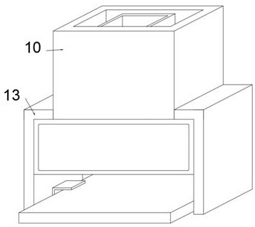
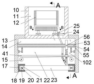
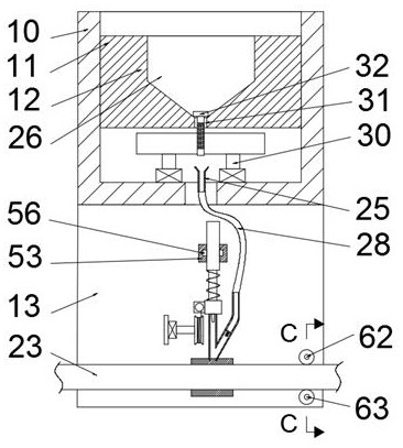
[0021] refer to Figure 1-9 , an automatic locking screw machine system according to an embodiment of the present invention, comprising a base 13, the base 13 is provided with a smooth cavity 14 that penetrates front and ba...


PUM


Abstract

The invention discloses an automatic screw locking machine system. The automatic screw locking machine system comprises a base, a smooth cavity penetrating front and back is formed in the base, first mounting blocks symmetrical in position are fixedly arranged on the left wall and the right wall of the smooth cavity, first sliding grooves with openings facing the symmetry center are formed in the first mounting blocks, and the first sliding grooves are slidably connected to first sliding blocks. According to the system, a controllable screw locking position adjusting device is arranged, the required screw locking position can be independently selected according to the requirement, a positioning device capable of conducting left-right positioning is arranged, the requirement for locking screws on different workpieces through the screw locking machine can be met, a screw locking depth of the screw locking machine can be achieved through a moving device, it is ensured that depths of locked screws are consistent, a conveying device is arranged to achieve automatic integration of the screw locking machine, labor intensity of workers is reduced, production quality and production efficiency are improved, universality is high, and the screw locking machine can be matched with industrial line operation.

Description

technical field [0001] The invention relates to the technical field of automatic locking screw machines, in particular to an automatic locking screw machine system. Background technique [0002] The automatic locking screw machine realizes the automatic conveying, tightening and testing of screws through various electric and pneumatic components, and simplifies the screw fastening process through equipment, so as to reduce the number of labor and reduce the adverse factors caused by manual misoperation. A typical non-standard automation equipment. The existing automatic screw locking machine requires the position of the locking screw to be as uniform as possible. The irregular position of the locking screw will cause difficulties in machine operation. The actual position of the locking screw deviates from the expected position, and the processing The quality of the finished products is not good, and the processing of the automatic locking screw machine needs to avoid problem...

Claims


Application Information

Patent Timeline
Patent Type & Authority Applications(China)
IPC IPC(8): B23P19/06
CPCB23P19/06
Inventor 林艺婷
Owner 厦门蕉承贸易有限公司
Why Eureka
Try Eureka