Compensation Method for Parameters Below Base Speed ​​of Permanent Magnet Synchronous Motor Based on Feedforward Voltage Compensation

A permanent magnet synchronous motor and parameter compensation technology, applied in the field of rail transit, can solve problems such as large calculation errors and complex calculation formulas, and achieve the effects of accurate transmission, reduction of calculation errors, and reduction of complexity

Active Publication Date: 2021-11-09
BEIJING JIAOTONG UNIV
View PDF5 Cites 0 Cited by
  • Summary
  • Abstract
  • Description
  • Claims
  • Application Information

AI Technical Summary

Problems solved by technology

However, this method requires that there must be a speed outer loop in the control. The current amplitude obtained through the adjustment of the speed outer loop can be combined with the calculated stator current angle for d-q axis current synthesis, which is not applicable to the control method with only the torque inner loop. And using the formula to directly calculate in the small torque condition will lead to a large calculation error, and the calculation formula is more complicated

Method used


Image

  • Compensation Method for Parameters Below Base Speed ​​of Permanent Magnet Synchronous Motor Based on Feedforward Voltage Compensation
  • Compensation Method for Parameters Below Base Speed ​​of Permanent Magnet Synchronous Motor Based on Feedforward Voltage Compensation
  • Compensation Method for Parameters Below Base Speed ​​of Permanent Magnet Synchronous Motor Based on Feedforward Voltage Compensation

Examples


Embodiment Construction

[0037] The present invention will be described in further detail below in conjunction with the accompanying drawings.

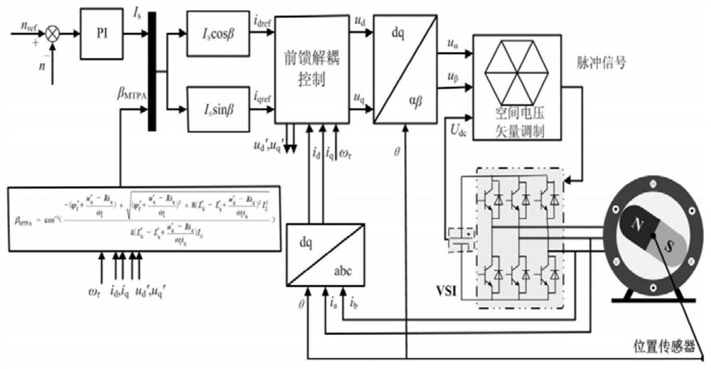
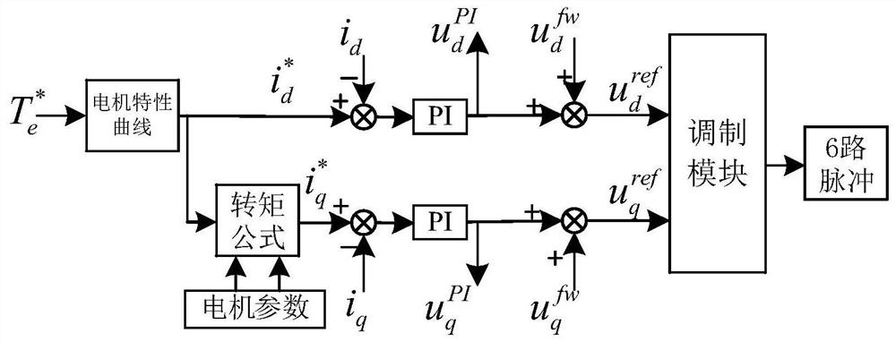
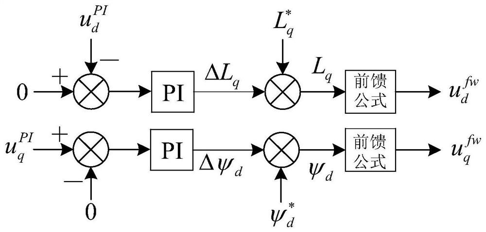
[0038] Such as figure 2 , 3 As shown, the present invention is based on the compensation method for parameters below the base speed of the permanent magnet synchronous motor based on feedforward voltage compensation. The specific steps are as follows:

[0039] S1. Obtain the DC bus voltage U through the voltage and current sampling circuit dc and three-phase current i a i b i c , the rotor position angle θ is obtained through the resolver decoding circuit;

[0040] Then transform the three-phase current from the three-phase stationary coordinate system to the two-phase synchronous rotating coordinate system to obtain the d-axis current i d and q-axis current i q , the transformation matrix is:

[0041]

[0042]Calculate the motor speed ω from the rotor position angle θ s , the calculation formula is:

[0043]

[0044] S2. The motor control me...


PUM


Abstract

The invention relates to a method for compensating parameters below the base speed of a permanent magnet synchronous motor based on feedforward voltage compensation, comprising: S1. calculating d-axis current and q-axis current; S2. calculating d-axis current command through torque command; S3 .Through the current loop PI regulator to obtain and S4 respectively. Calculate and and respectively and sum to obtain and S5. And input to the space vector modulation module to obtain 6 pulses, which act on the voltage type inverter to control the motor; S6. The q-axis inductance and d-axis flux linkage are compensated; the compensated q-axis inductance and d-axis flux linkage are used for the calculation of step S2 and step S4 in the next calculation cycle; the reciprocating cycle of step S1-S6 is through the compensation of the motor parameters Achieve precise control of motor output torque.

Description

technical field [0001] The invention relates to the field of rail transit, in particular to a method for compensating parameters of a permanent magnet synchronous motor below a base speed based on feedforward voltage compensation in a rail transit traction system. Background technique [0002] Permanent magnet synchronous motors have the advantages of high power density, high power factor, high efficiency, and small size, and are widely used in rail transit traction systems. The main control method of permanent magnet synchronous motor is vector control based on synchronous rotating coordinate system (d-q axis), which is suitable for operating conditions in the full speed range. [0003] The core control object of the permanent magnet synchronous motor is the torque. In order to ensure the accurate issuance of the torque command, accurate motor parameters are required. In order to obtain more accurate motor parameters, the main method currently used is the online parameter ...

Claims


Application Information

Patent Timeline
Patent Type & Authority Patents(China)
IPC IPC(8): H02P21/16H02P21/14H02P21/22H02P25/022H02P27/12
CPCH02P21/141H02P21/16
Inventor 王琛琛张梓绥周明磊游小杰王剑江龙谢冰若
Owner BEIJING JIAOTONG UNIV
Why Eureka
Try Eureka