
Amorphous metal thin strip, laminated core, and amorphous metal thin ribbon punching method

A technology of metal sheet and processing method, which is applied in the direction of magnetic core manufacturing, magnetic core/yoke, transformer/inductor parts, etc. Cutting workability, low manufacturing cost, and application-promoting effect

Active Publication Date: 2021-10-15
株式会社博迈立铖
View PDF10 Cites 0 Cited by
  • Summary
  • Abstract
  • Description
  • Claims
  • Application Information

AI Technical Summary

Problems solved by technology

That is, when the core is manufactured from an amorphous metal thin strip, the number of laminations increases, and accordingly, the number of times of punching also increases.

Method used


Image

  • Amorphous metal thin strip, laminated core, and amorphous metal thin ribbon punching method
  • Amorphous metal thin strip, laminated core, and amorphous metal thin ribbon punching method
  • Amorphous metal thin strip, laminated core, and amorphous metal thin ribbon punching method

Examples


Embodiment 1

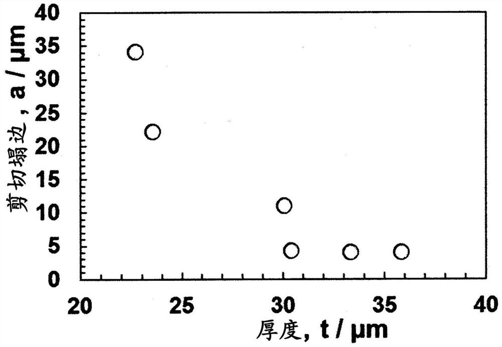
[0074] Manufactured alloy composition in atomic % Fe by roll cooling 81.5 Si 4 B 14.5thin strips of amorphous metal. Regarding the amorphous metal ribbon, as shown in Table 1, an amorphous metal ribbon having a thickness in the range of 22.7 μm to 35.8 μm was prepared. The thickness of the ribbon is calculated from density and weight and dimensions (length x width). In addition, the width of the thin strip was 80 mm.

[0075] As the blanking die, a superhard material (FUJILOY VF-12 material manufactured by Fuji Mold Co., Ltd.) was used for both the punch and the die. The punch is a rectangular column with a front end, its size is 5×15mm, and the R part is 0.3mm. The die is formed with a machined hole into which the punch is inserted.

[0076] Amorphous metal thin strips of various thicknesses were placed on the die in a stacked state, and were driven under a load of 1400N to perform punching. Then, amorphous metal flakes having different thicknesses of 5×15 mm were fabr...

Embodiment 2

[0086] An amorphous metal ribbon having the alloy composition and thickness shown in Table 2 was produced by roll cooling. This amorphous metal ribbon was punched in the same manner as in Example 1 to produce individual amorphous metal flakes.

[0087] In particular, when Al, Sn, and Ni are added to the alloy composition, the width of the sag becomes smaller.

[0088] In Fe-based amorphous alloys, a tendency to segregate a large amount of Al or the like (Al, Sn, Ni, Cu, Cr, Mn) in the oxide film on the surface has been confirmed. Surface segregation of Al tends to cause so-called surface crystallization in which crystal grains grow in a dendritic form starting from agglomerated Al clusters. When heat treatment is performed in a magnetic field for the purpose of imparting induced magnetic anisotropy, the tape whose surface has undergone crystallization cannot be effectively imparted with induced magnetic anisotropy, and the coercive force Hc tends to increase. An increase in ...


PUM

PropertyMeasurementUnit
thicknessaaaaaaaaaa
thicknessaaaaaaaaaa
Vickers hardnessaaaaaaaaaa

Abstract

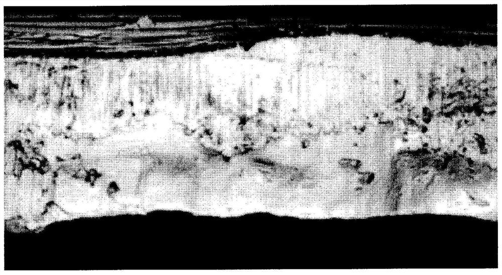
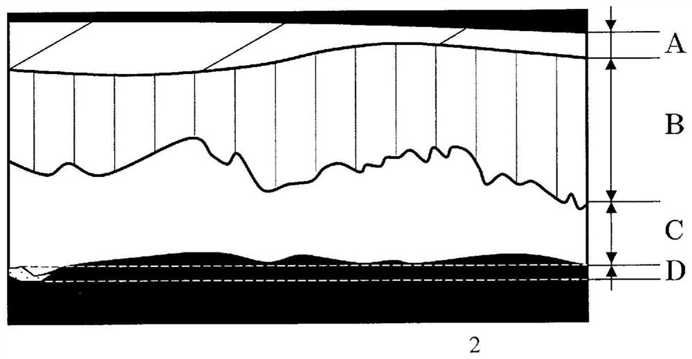
Provided are a punching method demonstrating excellent amorphous metal thin ribbon punching performance, and an amorphous metal thin strip and a laminated core produced by same. The amorphous metal thin strip has a metal thin strip thickness that is thicker than 30 (mu)m but no greater than 50 (mu)m. The metal thin strip has a side surface comprising a punched surface wherein at least a droop, a shear cross-section, and a fracture cross-section are observed. Within the side surface, the droop width relative to the metal thin strip thickness is no more than 30%.

Description

technical field [0001] The present invention relates to a punching method of an amorphous metal sheet, a laminated core, and an amorphous metal strip used as a laminated core for a motor or an antenna. Background technique [0002] Worldwide, the electric power consumption of the electric motor is considered to be about half of the total electric power consumption. The electric power loss in the motor is roughly divided into core loss, copper loss, and mechanical loss in the motor core. When focusing only on the core loss, the material is required to have good soft magnetic properties. [0003] At present, the main soft magnetic material used in the motor core is non-oriented electrical steel sheet. However, in recent years, amorphous metal thin strips having very good soft magnetic properties compared with non-oriented electrical steel sheets have attracted attention, and have begun to be put into practical use in limited applications. It is clear that if the application...

Claims


Application Information

Patent Timeline
Patent Type & Authority Applications(China)
IPC IPC(8): B21D28/00C22C45/02H01F41/02H01F1/153H01F27/245
CPCC22C45/02H01F41/024H01F3/02H01F41/0226H01F1/15308B21D28/02B21D28/26B21D33/00Y02T10/64C22C2202/02H01F1/153H01F41/02
Inventor 太田元基
Owner 株式会社博迈立铖
Learn More