Automatic injection molding system and control method thereof

An automatic injection molding and injection molding system technology, applied in the direction of manufacturing tools, feeding devices, positioning devices, etc., can solve problems such as low automation, low production efficiency, and injection molding process errors, achieve excellent punching performance and save labor costs , The effect of improving processing efficiency

Pending Publication Date: 2020-11-06
东莞智奥自动化科技有限公司
View PDF0 Cites 0 Cited by
  • Summary
  • Abstract
  • Description
  • Claims
  • Application Information

AI Technical Summary

Problems solved by technology

However, the inventor found that the existing injection molding system requires manual feeding, which is likely to cause errors in the injection molding process, which is not conducive to controlling the accuracy of product processing, and the existing injection molding system cannot take into account the processing procedures of punching, injection molding, and testing. , the degree of automation is low, the production efficiency is low, and it cannot meet the needs of processing and production

Method used


Image

  • Automatic injection molding system and control method thereof
  • Automatic injection molding system and control method thereof
  • Automatic injection molding system and control method thereof

Examples


Embodiment 1

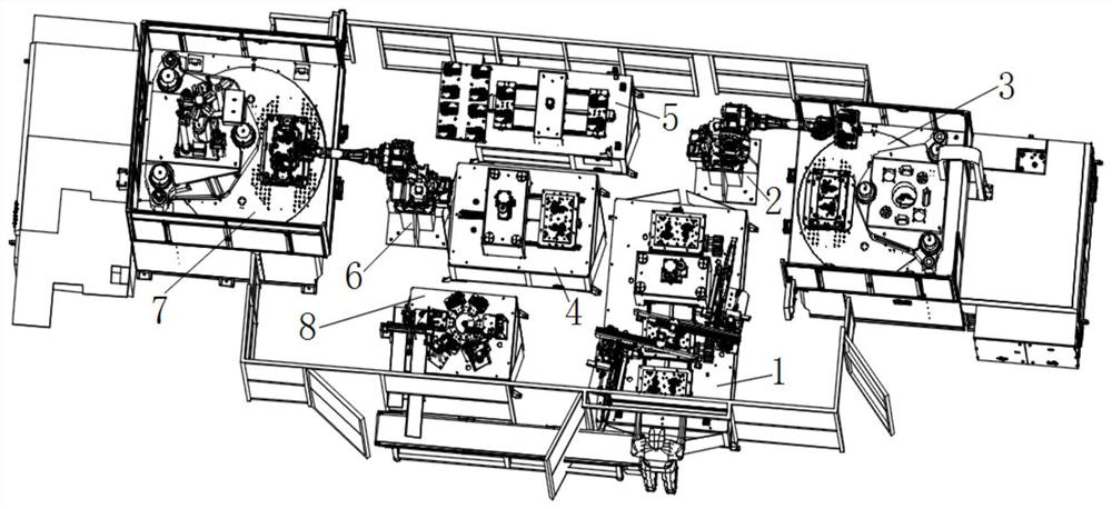
[0040] An automatic injection molding system, including a first punching device 1, a first pick-and-place device 2, a first injection device 3, a second punching device 4 and a first testing device 5, the first punching device 1 is used for punching Cut the metal parts to be processed, the first pick-and-discharge device 2 is used to transfer the metal parts, and the metal parts pass through the first pick-and-discharge device 2 from the first punching device 1 to the first injection molding device 3 and the second punching device 4 and the first testing device 5, the second punching device 4 is used to process the part of the punched metal piece that is not punched by the first punching device 1, the first punching device 1, the first injection molding device 3, the second The punching device 4 and the first testing device 5 surround the first pick-and-discharge device 2, thereby improving the moving efficiency of the first pick-and-discharge device 2, and the metal piece pass...

Embodiment 2

[0054] A control method for an automatic injection molding system, comprising the following steps:

[0055] S1. Place the metal piece to be processed in the first punching device 1, and the first punching device 1 punches and processes the metal piece;

[0056] S2. The first loading and unloading device 2 transfers the punched metal parts from the first punching device 1 to the first injection device 3, and the first injection device 3 injects the punched metal parts;

[0057] S3. The first pick-and-place device 2 transfers the injected metal parts from the first injection device 3 to the second punching device 4, and the second punching device 4 punches the injected metal parts to form the metal parts to be formed. Check metal parts;

[0058] S4. The first pick-and-place device 2 transfers the metal piece to be inspected from the second punching device 4 to the first testing device 5, and the first testing device 5 detects the quality of the metal piece to be inspected.

[...


PUM


Abstract

The invention belongs to the technical field of automatic equipment and particularly relates to an automatic injection molding system. The automatic injection molding system comprises a first punchingcutting device, a first material fetching and placing device, a first injection molding device, a second punching cutting device and a first testing device, wherein the first punching cutting deviceis used for punching and cutting a to-be-machined metal part, the first material fetching and placing device is used for transferring the metal part, and the metal part passes through the first injection molding device, the second punching cutting device and the first testing device in sequence from the first punching cutting device through the first material fetching and placing device. By meansof the automatic injection molding system, the metal part punching cutting and injection molding machining automation degree can be effectively improved, the system running controllability is significantly enhanced, the metal part punching cutting and injection molding effect can be detected in time, and the metal part punching cutting and injection molding machining quality is also improved. Meanwhile, the invention further provides a control method for the automatic injection molding system.

Description

technical field [0001] The invention belongs to the technical field of automation equipment, and in particular relates to an automatic injection molding system and a control method thereof. Background technique [0002] In the process of combining metal parts and plastic parts, the injection molding machine can fill the metal parts with plastic, so that the metal parts and plastic parts can be combined to form the required processed products. However, the inventor found that the existing injection molding system requires manual feeding, which is likely to cause errors in the injection molding process, which is not conducive to controlling the accuracy of product processing, and the existing injection molding system cannot take into account the processing procedures of punching, injection molding, and testing. , the degree of automation is low, the production efficiency is low, and it cannot meet the needs of processing and production. [0003] For this reason, it is urgent ...

Claims


Application Information

Patent Timeline
Patent Type & Authority Applications(China)
IPC IPC(8): B29C45/14B29C45/42B29C45/17B29C45/76B21D28/14B21D43/20B21C51/00
CPCB21C51/00B21D28/14B21D43/20B29C45/14B29C45/14008B29C45/1769B29C45/4225B29C45/76B29C2045/14868B29C2045/425B29C2945/7629
Inventor 李理旭华庆荣郭秀臻温武林杨华芳姚爱武
Owner 东莞智奥自动化科技有限公司
Why Eureka
Try Eureka