Pruning device and using method

A technology of control device and rolling scissors, which is applied in the field of mechanical processing, can solve the problems of affecting processing efficiency, time-consuming and labor-intensive, cutting edge damage, disassembly and maintenance, etc.

Pending Publication Date: 2021-10-19
苏州云刚智能科技有限公司
View PDF18 Cites 0 Cited by
  • Summary
  • Abstract
  • Description
  • Claims
  • Application Information

AI Technical Summary

Problems solved by technology

[0004] The purpose of the present invention is to provide a trimming device, which is used to solve the problem that in the prior art, when using a punch press to cut the redundant steel wire heads on both sides of the f

Method used


Image

  • Pruning device and using method
  • Pruning device and using method
  • Pruning device and using method

Examples


Embodiment 1

[0104] [Example 1]

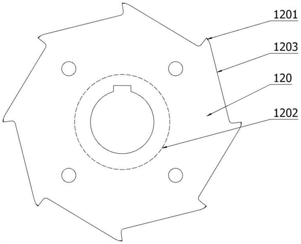
[0105] Such as figure 1 As shown, this embodiment discloses a rolling scissors, including: a body 120, the body 120 is used to connect the control device 150; an engaging part 1203, the engaging part 1203 is connected with the body 120, and the engaging part 1203 is used to attach parts ; The cutting part 1201, the cutting part 1201 is connected with the main body 120, and the cutting part 1201 is used for cutting materials.

[0106] Specifically, a placement portion 1202 for connecting the control device 150 is provided on the surface of the body 120 . The placement portion 1202 is lower than the surface of the body 120 . The placement part 1202 is set in a circular shape, and a keyway is arranged in the middle of the placement part 1202, the keyway is a through hole, and the keyway is composed of a circular hole and a rectangular hole. The surface of the main body 120 is provided with a fixing hole 2011, and the fixing hole 2011 is circular. The fixi...

Embodiment 2

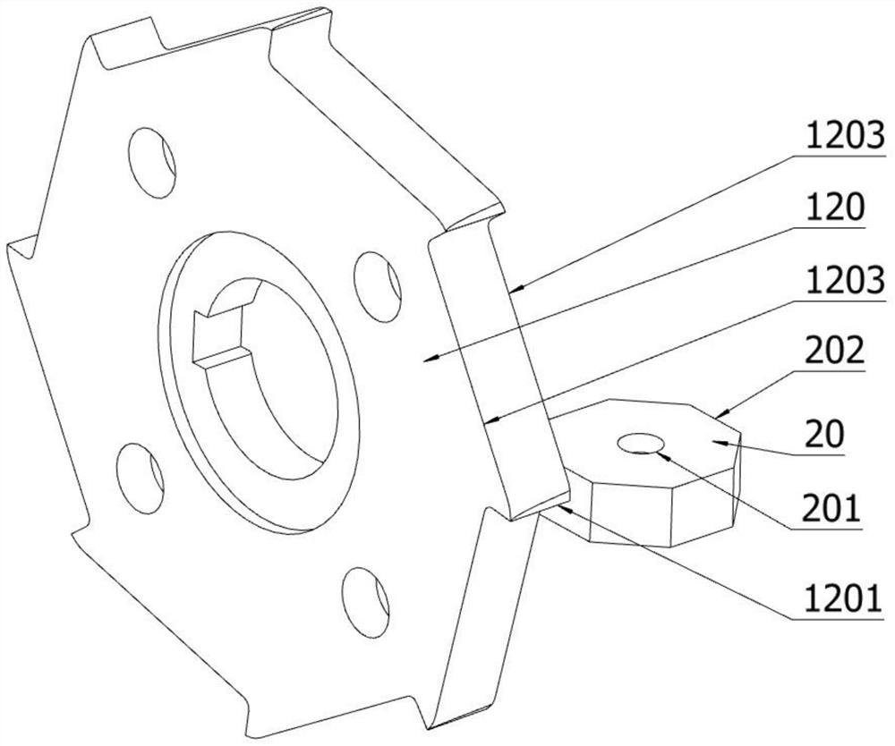
[0108] Such as image 3 , 5 As shown, the embodiment of the present application discloses a rolling shear assembly, including: a body 120, the body 120 is used to connect the control device 150; Integral structure, the engaging part 1203 is used to attach parts; the cutting part 1201, the cutting part 1201 is connected with the main body 120, the cutting part 1201 and the main body 120 are integrally formed, and the cutting part 1201 is used for cutting materials.

[0109] In the above technical solution, in order to solve the problem of using a punch press to cut the excess steel wire heads on both sides of the fence mesh, the punch press occupies a very large area, and the cutting edge of the punch press is damaged, and it takes time and effort to disassemble and maintain, which affects the processing efficiency. This application adopts features such as the phantom body 20 and the cutting part 1201 for assembly. By setting an angle at the joint between the phantom body 20 a...

Embodiment 3

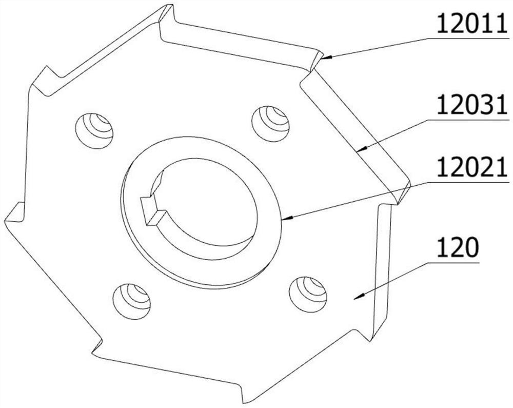
[0117] Such as figure 2 , 4 As shown, this embodiment discloses a trimming device, which includes: a body 120, the body 120 is used to connect the geared motor; The wall 12031 is used to fit the mold body; the hob head 12011, the hob head 12011 is connected with the body 120, the hob head 12011 and the body 120 are integrally formed, and the hob head 12011 is used for cutting the object to be cut; the control device 150, the control device 150 is disposed on one side of the body 120 , and the control device 150 is fixedly connected to the body 120 .

[0118] In the above technical solution, in order to solve the problem of using a punch press to cut the excess steel wire heads on both sides of the fence mesh, the punch press occupies a very large area, and the cutting edge of the punch press is damaged, and it takes time and effort to disassemble and maintain, which affects the processing efficiency. The application adopts base 280, mold body 20, mesh pressing plate 50, etc...


PUM


Abstract

The invention discloses a pair of rolling scissors, and relates to the technical field of machining. In the application, the rolling scissors comprise a body, a clamping part and a cutting part, wherein the body is used for being connected with a control device; the clamping part is connected with the body, and the clamping part is used for being attached to a part; and the cutting part is connected with the body, and the cutting part is used for cutting materials. The rolling scissors are used for preventing the problems that when a punch is used for cutting redundant steel wire ends at two sides of a fence mesh, the occupied area of the punch is very large, time and labor are wasted after a cutting edge is damaged during cutting of the punch, and the machining efficiency is affected.

Description

technical field [0001] The invention relates to the technical field of mechanical processing, in particular to a trimming device and a use method. Background technique [0002] With the progress in the field of mechanical processing technology, the processing requirements of the workpiece to be processed are also increasing, and the mechanism of the cutting process is also becoming more and more diversified. In the case of multi-variety mesh and small batch production, the processing is completed by adding equipment or manual cutting. The task will obviously increase the cost of work or reduce the efficiency of processing. [0003] In order to improve production efficiency, reduce manual operations, and improve the accuracy of processed parts, etc., CNC punching machines are usually used to cut meshes. However, CNC punching machines are large in size and difficult to move once installed. At the same time, CNC punching machines The precision of the mold is high. When there i...

Claims


Application Information

Patent Timeline
IPC IPC(8): B21F33/00B21F23/00B26D1/00B26F1/44B26D5/08B26D7/02B26D7/20B26D7/26B27G13/08B27C5/02B27C5/06B23D31/00
CPCB21F33/005B21F23/005B26D1/0006B26F1/44B26D5/086B26D7/02B26D7/20B26D7/2621B26D7/2635B27G13/08B27C5/02B27C5/06B23D31/00B26D2001/0033B26D2001/0053B26D2001/006B26D2001/0066
Inventor 朱赟施士清华叙亮顾卫忠王荣
Owner 苏州云刚智能科技有限公司
Why Eureka
Try Eureka