Truss type garbage compression station

A garbage compression station and garbage compressor technology, applied in the direction of presses, manufacturing tools, etc., can solve the problem of high cost of compressed garbage bins, garbage compressors cannot use multiple garbage bins, garbage compressors and garbage bins cannot be separated, etc. problems, to achieve the effect of reducing waste disposal costs, low cost, and reduced transshipment steps

Pending Publication Date: 2021-10-19
重庆捌拾玖度环保科技有限公司
View PDF0 Cites 3 Cited by
  • Summary
  • Abstract
  • Description
  • Claims
  • Application Information

AI Technical Summary

Problems solved by technology

[0004] The object of the present invention is to provide a truss-type garbage compression station to solve the problem that the existing compressed garbage bins are expensive, and the garbage compressor and the garbage bin cannot be separated because the garbage compressor cannot be used for multiple garbage bins. question

Method used


Image

  • Truss type garbage compression station
  • Truss type garbage compression station
  • Truss type garbage compression station

Examples


Embodiment 1

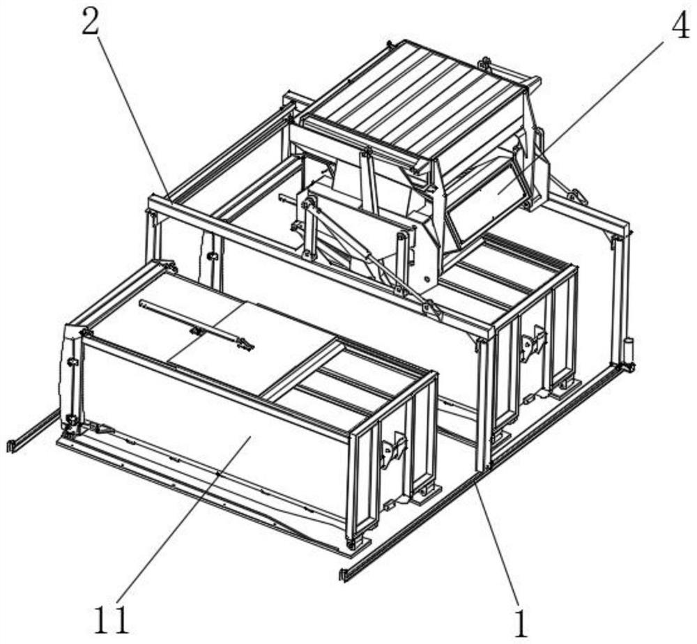
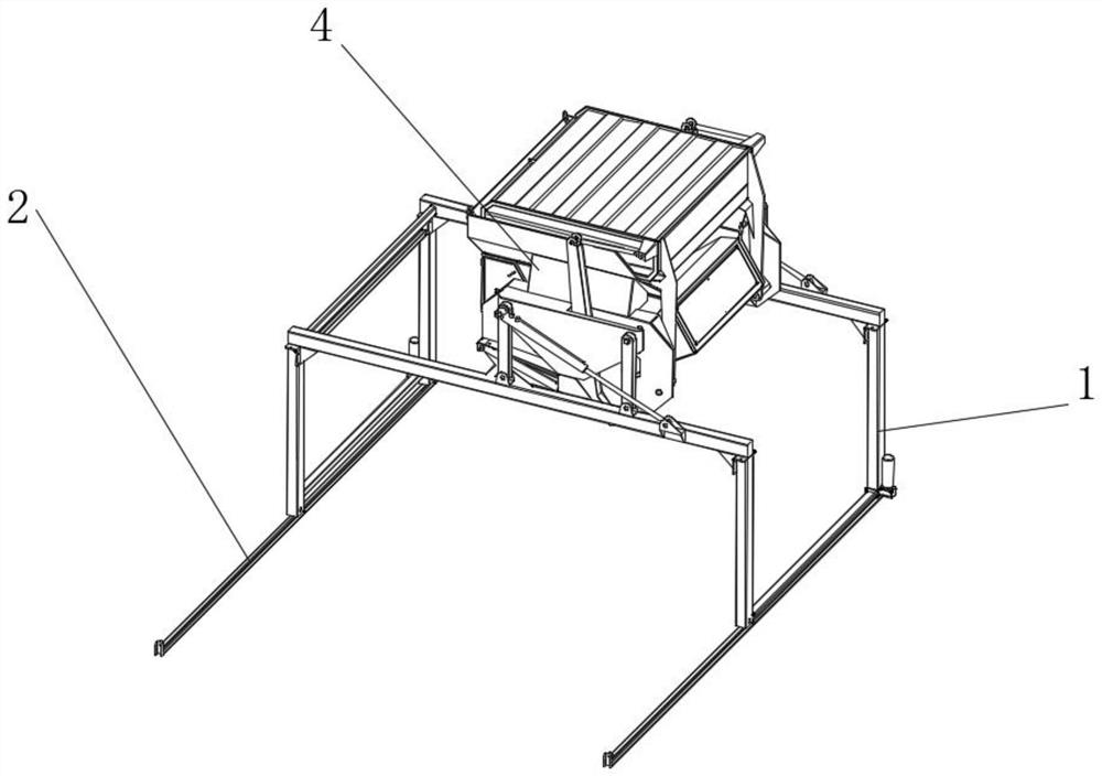
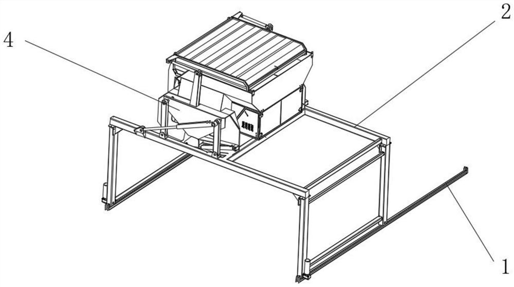
[0036] Such as figure 1 , 2 As shown in and 3, the device includes two parallel guide rails 1 fixed on the ground, two mobile trusses 2 installed on the two parallel guide rails 1, and a garbage compressor 4 installed on the mobile truss 2, and the mobile truss 2 is an upside-down "U" shape, and at least one reinforcing beam is arranged between two moving trusses 2, and the reinforcing beam is located on the other side of the loading direction of the garbage compressor 4, and the moving truss 2 is provided at the bottom with the guide rail 1 Cooperating driving wheel, the driving wheel is driven by a hydraulic motor or an electric motor, the driving wheel is a chute or a rack, and the guide rail 1 is correspondingly provided with a chute or a rack, preferably the guide rail 1 is a raised slide rail, and the driving wheel is The grooved wheel that cooperates with the guide rail 1, the two sides of the guide rail 1 are provided with bars to prevent the driving wheel from fallin...

Embodiment 2

[0042] The difference between Embodiment 2 and Embodiment 1 is that the guide rail 1 is installed on the wall or the roof, the guide rail 1 is installed on the wall, beam or roof through a plurality of fixed brackets, and the driving wheels on the truss 2 are suspended on the guide rail 1 , the driving wheel is hung on the inside or outside of the two guide rails, and a fixed beam is provided on the moving truss 2 to fix the distance between the driving wheels, making it easier to hang the driving wheels on the guide rails, and it can also be used in the movement of the driving wheels Barriers are set on both sides of the direction, which are used to guide and limit the movement of the drive wheel. When the guide rail 1 is hung on the roof and the wall, the guide rail 1 is fixed by a plurality of vertical beams, and a fixed base and reinforcement ribs are provided at the fixed connection between the vertical beam and the roof. , increase the triangular oblique tension rod to i...


PUM


Abstract

The invention relates to the field of garbage treatment, in particular to a truss type garbage compression station. The truss type garbage compression station comprises at least one guide rail, at least two movable trusses installed on the guide rail and a garbage compressor installed on the movable trusses, wherein the garbage compressor is connected to the movable truss through a plurality of connecting rods; a lifting hydraulic cylinder is arranged at the end, hinged to one connecting rod, of the garbage compressor, the other end of the lifting hydraulic cylinder is fixed to the movable truss, and the lifting hydraulic cylinder drives the connecting rods to swing to achieve lifting of the lifting garbage compressor; and the end, connected with the guide rail, of the movable truss is provided with a driving wheel, and the driving wheel drives the movable truss to move on the guide rail. The garbage compressor is separated from garbage cans, one garbage compressor can be used for garbage compression of the multiple garbage cans, compared with a compression type garbage can, the cost is greatly reduced, the garbage compressor does not need to be transferred when the garbage cans are transferred, and the garbage treatment cost is indirectly reduced.

Description

technical field [0001] The invention relates to the field of garbage disposal, in particular to a truss type garbage compression station. Background technique [0002] Municipal waste can be compressed to reduce its volume, which is convenient for transportation and landfill. Among them, the compressed garbage bin not only has the functions of airtightness, deodorization, compression, storage, etc., but also is beautiful and environmentally friendly. It has been widely used in garbage compression treatment. [0003] The traditional garbage bin mainly plays the role of storing garbage, does not have the function of compression, and the volume utilization rate of the garbage bin is low; the existing compressed garbage bin integrates the garbage compressor and the garbage bin, which combines the garbage The design of combining garbage bins solves the problems of garbage compression and garbage bin volume utilization, but the cost is relatively high, and each garbage bin needs ...

Claims


Application Information

Patent Timeline
Patent Type & Authority Applications(China)
IPC IPC(8): B30B9/30
CPCB30B9/3092B30B9/301B30B9/3057B30B9/3042B30B9/3003B30B9/3021
Inventor 冯汝云傅浪
Owner 重庆捌拾玖度环保科技有限公司
Why Eureka
Try Eureka