Water rocket's pressure-activated parachute opening device

A water rocket, pressure-driven technology, applied in the field of pressure-driven parachute parachute opening devices, can solve the problems of poor repeatability, high cost, impact, etc.

Active Publication Date: 2022-05-03
NAT UNIV OF DEFENSE TECH
View PDF0 Cites 0 Cited by
  • Summary
  • Abstract
  • Description
  • Claims
  • Application Information

AI Technical Summary

Problems solved by technology

The disadvantage of the parachute opening device of the water rocket in this scheme is: the connection between the timer connecting rod and the elastic rope is unstable, and it is difficult to realize stable carrying and accurate release near the highest point at the same time during the ascent process; the torsion spring itself has an idling stroke Poor, it needs to rely on the operator's experience to set the timer manually before each flight, the action triggering accuracy is low, and the repeatability is poor; through actual flight measurement, the average time error of this kind of device to perform the parachute separation action is about 1 second, and the maximum time error up to 5 seconds
The disadvantage of the parachute opening device of the water rocket in this scheme is that the device system needs to include sensors, actuators, control boards, power supplies, etc., and the system is bulky and complicated; COTS devices generally do not have special waterproof treatment, and require mechanical, electrical and waterproof integration Modernized design, complex system and high cost
[0014] Therefore, it is difficult for the parachute opening devices of water rockets in the prior art to simultaneously meet the above three basic design requirements of ① can work independently; ② strong reliability and high accuracy of action triggering;

Method used


Image

  • Water rocket's pressure-activated parachute opening device
  • Water rocket's pressure-activated parachute opening device
  • Water rocket's pressure-activated parachute opening device

Examples


Embodiment Construction

[0033] In order to make the purpose, technical solution and advantages of the present invention clearer, the technical solution of the present invention will be clearly and completely described below in conjunction with specific embodiments of the present invention and corresponding drawings. Apparently, the described embodiments are only some of the embodiments of the present invention, but not all of them. Based on the embodiments of the present invention, all other embodiments obtained by persons of ordinary skill in the art without making creative efforts fall within the protection scope of the present invention.

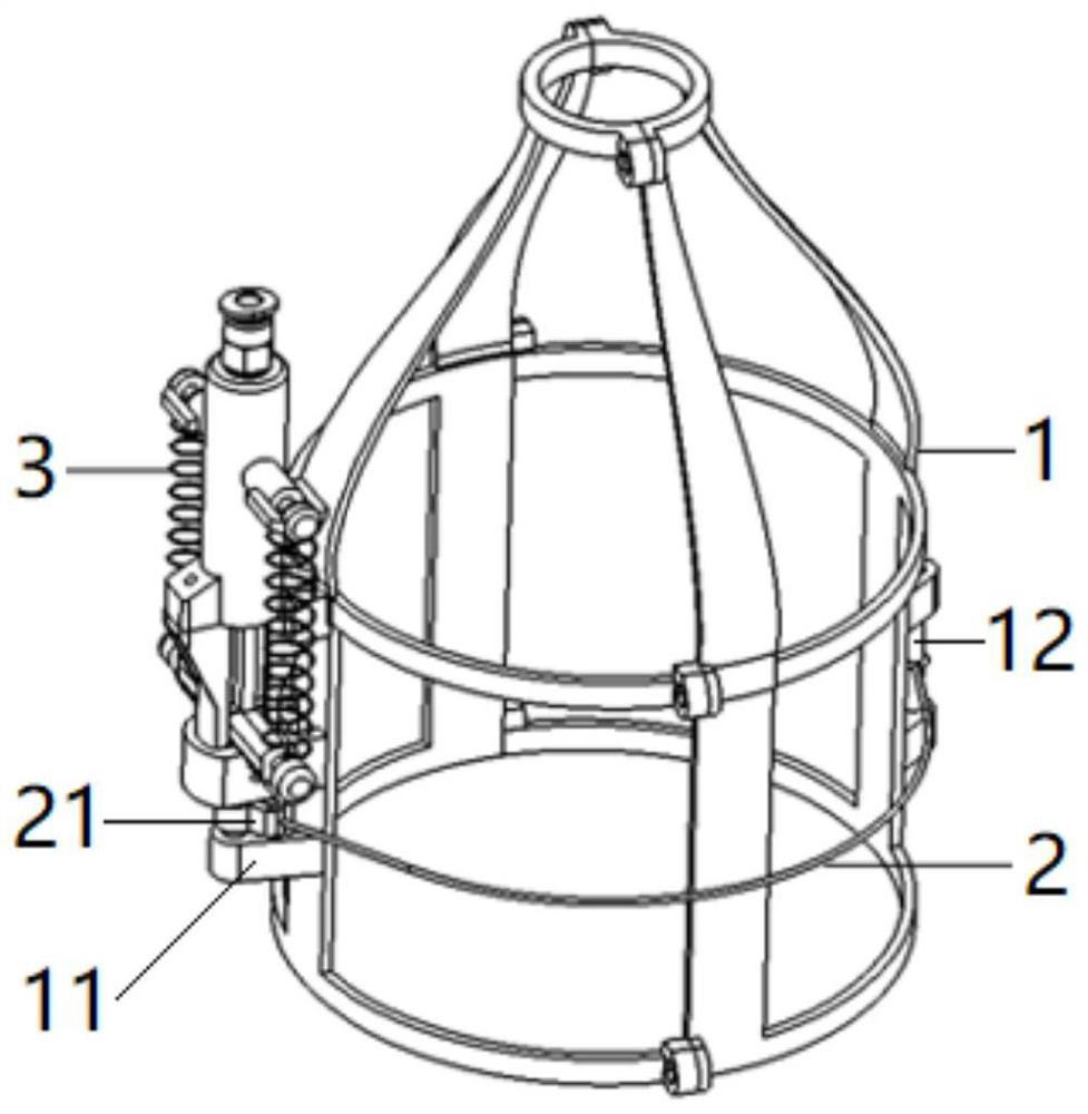
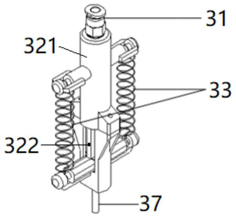
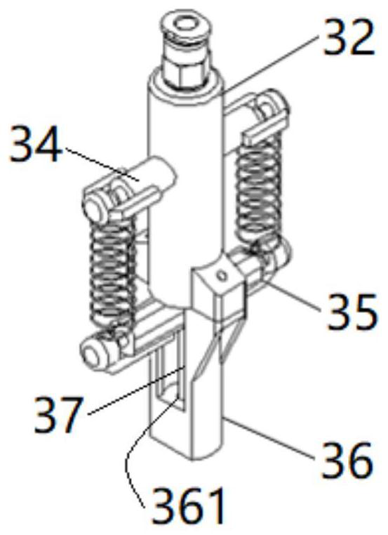
[0034] Such as figure 1 , shown in Fig. 2 (a) and Fig. 2 (b), Fig. 3 (a) and Fig. 3 (b), the pressure-type parachute parachute opening device of water rocket of the present invention comprises: be fixed on the water rocket rocket body upper end The connection base 1; the elastic fixing rope 2 used to bind and fix the parachute during the flight of the water roc...


PUM


Abstract

A pressure-activated parachute opening device for a water rocket, comprising a connection base, an elastic fixed rope, and a piston-spring mechanism; the side of the connection base is longitudinally equipped with a piston-spring mechanism and a convex There is a carbon fiber anchor bolt on the other side; one end of the elastic fixed rope is fixed to the anchor bolt, and the other end is connected to a collar; the piston-spring mechanism includes a soft air joint, a cylinder-piston assembly composed of a cylinder and a piston , extension spring, extension spring fixed hanging rod, extension spring movable hanging rod, extension spring movable hanging rod limiter, carbon fiber latch, the fixed hanging rod is fixed on the upper part of the outer wall of the cylinder, and the movable hanging rod is connected to the working end of the piston; The spring is hooked between the fixed hanging rod and the movable hanging rod; the limiter is arranged at the lower part of the cylinder; the upper end of the bolt is fixed on the movable hanging rod, and is compatible with the collar. The device of the invention satisfies the design requirements of independent work, strong reliability, high action triggering precision, moisture resistance and water pressure impact resistance.

Description

technical field [0001] The invention belongs to the technical field of power aviation, and in particular relates to a pressure-activated parachute opening device for a water rocket. Background technique [0002] The water rocket assisted glider is a common combined power aviation model. This model is mainly composed of a water rocket, a fixed-wing glider, and a connection-separation device between the two. Generally, a parachute opening device is required to be installed on the water rocket body. Water rocket-assisted glider is often used in the flight test of small and medium-sized fixed-wing glider models, and the teaching of aerospace professional engineering practice. It is also one of the main competition items in the China International Aircraft Design Challenge. [0003] The working process of the water rocket-assisted glider is similar to that of the launch vehicle: in the boosting ascent phase, the water rocket carries the glider into the sky and separates the glid...

Claims


Application Information

Patent Timeline
Patent Type & Authority Patents(China)
IPC IPC(8): B64D17/70B64D17/62
CPCB64D17/70B64D17/62
Inventor 梁昊鹏赵勇谢士娇陈德峻张海栋
Owner NAT UNIV OF DEFENSE TECH
Why Eureka
Try Eureka