
Structure for generating distributed suction vortexes

A distributed and vortex technology, applied in the field of machinery, can solve problems such as compressor surge, blade stall flutter, and limited range of tangential speed increase of compressor rotor blade tip, so as to improve control efficiency and reduce separation flow

Active Publication Date: 2021-10-19
HARBIN INST OF TECH
View PDF7 Cites 0 Cited by
  • Summary
  • Abstract
  • Description
  • Claims
  • Application Information

AI Technical Summary

Problems solved by technology

At present, due to the constraints of materials and structural conditions, due to safety considerations, the tangential velocity of the compressor rotor blade tip is limited. To further increase the aerodynamic load will cause serious flow separation in the cascade, reduce the efficiency of the cascade and even cause Stall flutter of the blades or surge of the compressor, leading to serious accidents

Method used


Image

  • Structure for generating distributed suction vortexes
  • Structure for generating distributed suction vortexes
  • Structure for generating distributed suction vortexes

Examples


Embodiment Construction

[0022] In order to make the purposes, technical solutions and advantages of the embodiments of the present application clearer, the technical solutions in the embodiments of the present application will be clearly and completely described below in conjunction with the drawings in the embodiments of the present application. Obviously, the described embodiments It is a part of the embodiments of this application, but not all of them. Based on the embodiments in the present application, all other embodiments obtained by persons of ordinary skill in the art without making creative efforts belong to the protection scope of the present application.

[0023] The following discussion provides several embodiments of the application. Although each embodiment represents a single combination of the application, different embodiments of the application can be replaced or combined in combination, so the application can also be considered to include all possible combinations of the same and / ...


PUM


Abstract

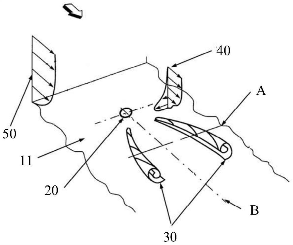
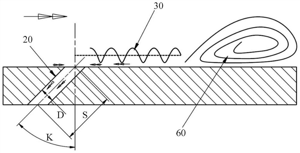
The invention provides a structure for generating distributed suction vortexes. The structure comprises a base body and suction holes. The base body has a working surface on which flow separation of gas can be generated. The suction holes are formed in the base body, and the pressure of the ends, located on the working surface, of the suction holes is larger than that of the ends, away from the working surface, of the suction holes. According to the structure, when gas flows through the working surface of the structure and passes through the suction holes, low-energy fluid in the gas can be discharged from the suction holes to reduce separation flow, and meanwhile, the fluid in the direction perpendicular to the gas movement direction can be sucked into the suction holes, so that the gas generates transverse flow in the direction perpendicular to the gas movement direction; under the action of the transverse flowing gas, the gas passes through the suction holes and then symmetrically forms two vortexes in the separation area, and the two vortexes can improve the kinetic energy of the gas, so that the reverse pressure gradient resistance of the gas is improved, the separation flow is reduced, and the control efficiency of flow separation is improved.

Description

technical field [0001] The present application relates to the field of mechanical technology, in particular to a structure for generating distributed suction vortices. Background technique [0002] In recent years, the rapid development of aero-engines and gas turbines has put forward requirements for compressor components with higher pressure ratio, higher efficiency and stable working range without exception. At present, due to the constraints of materials and structural conditions, due to safety considerations, the tangential velocity of the compressor rotor blade tip is limited. To further increase the aerodynamic load will cause serious flow separation in the cascade, reduce the efficiency of the cascade and even cause Stall flutter of the blades or surge of the compressor, leading to serious accidents. Contents of the invention [0003] The object of the present application is to provide a structure for generating distributed suction vortices that reduces gas separa...

Claims


Application Information

Patent Timeline
Patent Type & Authority Applications(China)
IPC IPC(8): F04D29/66
CPCF04D29/667
Inventor 周逊李柏罗磊杜巍
Owner HARBIN INST OF TECH
Learn More