Eureka AIR delivers breakthrough ideas for toughest innovation challenges, trusted by R&D personnel around the world.

Manual valve centering structure

A manual valve and valve body technology, applied to valve details, valve devices, engine components, etc., can solve the problems of complex dual-piston compound structure, affecting the movement of the device back to the center, and difficult processing, etc., to achieve high reliability and smooth movement , adjust the precise effect

Active Publication Date: 2021-10-19
邳州宏盛液压元件有限公司
View PDF6 Cites 0 Cited by
  • Summary
  • Abstract
  • Description
  • Claims
  • Application Information

AI Technical Summary

Problems solved by technology

[0004] There are two deficiencies in the above-mentioned technology: first, the driving rod is a swinging motion, and the end of the driving rod is an arc-shaped stroke, and the driving rod has a relative rotation tendency with the first piston or the second piston moving in a straight line, which affects the centering of the device. Movement; the composite structure of the double piston is too complicated, and the processing is difficult, resulting in an increase in cost

Method used


Image

  • Manual valve centering structure
  • Manual valve centering structure

Examples


Embodiment Construction

[0018] The following will clearly and completely describe the technical solutions in the embodiments of the present invention with reference to the accompanying drawings in the embodiments of the present invention. Obviously, the described embodiments are only some, not all, embodiments of the present invention. Based on the embodiments of the present invention, all other embodiments obtained by persons of ordinary skill in the art without making creative efforts belong to the protection scope of the present invention.

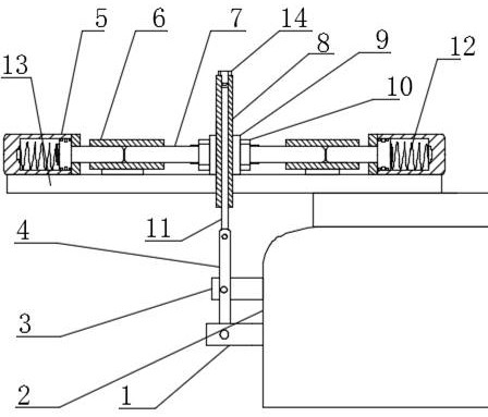
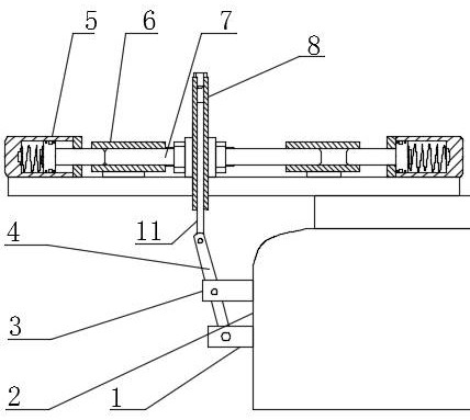
[0019] combine figure 1 and figure 2 As shown, one side of the valve body 2 protrudes from the valve stem 1, that is figure 1 A valve stem 1 protrudes from the left side of the middle valve body 2, and the valve core in the valve body 2 is controlled by the displacement of the valve stem 1. figure 1 The left side of the middle valve body 2 is fixed with a support plate 3, and the end of the valve stem 1 is connected with the figure 1 The lower end of the m...


PUM


Abstract

The invention discloses a manual valve centering structure, and belongs to the technical field of control valves. The manual valve centering structure comprises a valve body, a shifting rod and two oil cylinders which are symmetrically arranged; a piston rod of each oil cylinder is slidably sleeved with a guide sleeve; the two ends of a sliding rod are slidably sleeved with guide sleeves on the two sides respectively and abut against the corresponding oil cylinder piston rods; a core rod is hinged to the shifting rod and is vertically arranged; a sleeve pipe sleeves the core rod in a sliding manner; the middle of the sliding rod is sleeved with two clamping plates, and the two clamping plates clamp the two sides of the sleeve pipe; and two nuts used for fastening the clamping plates are further installed in the middle of the sliding rod. Swing of the shifting rod is converted into linear motion of the sleeve pipe through the guide sleeves, the sliding rod and the core rod, the sleeve pipe is controlled by the two oil cylinders to return to the middle position, the valve rod is driven to return to the middle position, motion is stable, the clamping phenomenon cannot occur, and reliability is high; and the position of the sleeve pipe can be directly adjusted through the clamping plates, the nuts, the guide sleeves and the sliding rod, the middle position of the valve rod is directly controlled, adjustment is more accurate, and efficiency is high.

Description

technical field [0001] The invention relates to the technical field of control valves, in particular to a manual valve centering structure. Background technique [0002] Manual valve is a control component in the pipeline fluid delivery system. It is used to change the passage section and medium flow direction, and has the functions of diversion, cut-off, regulation, throttling, check, diversion or overflow pressure relief. The lever of the manual valve is used to control the swing of the spool of the manual valve to realize the opening and closing of the valve. When the lever is in the neutral position, the valve is closed. Commonly used manual reversing valves, such as the reversing valves that control the rotation direction in construction machinery and the reversing valves that control the lifting and lowering of buckets in loaders, will have a back-to-center drive device. When not in operation, the reversing valve can be kept in the neutral position. The actuator does ...

Claims


Application Information

Patent Timeline
Patent Type & Authority Applications(China)
IPC IPC(8): F16K31/163
CPCF16K31/163F16K31/1221F16K31/1225
Inventor 沈克磊臧其刚陈梅
Owner 邳州宏盛液压元件有限公司
Why Eureka
Eureka Blog
Learn More