Bearing oiling device capable of preventing lubricating oil from overflowing
An oil injection device and lubricating oil technology, which is applied in the direction of lubricating oil input, lubricating parts, engine lubrication, etc., can solve the problems of low oil injection efficiency of bearings, grease overflow, etc., and achieve the effect of reducing labor intensity and avoiding overflow
- Summary
- Abstract
- Description
- Claims
- Application Information
AI Technical Summary
Problems solved by technology
Method used
Image
Examples
Embodiment 1
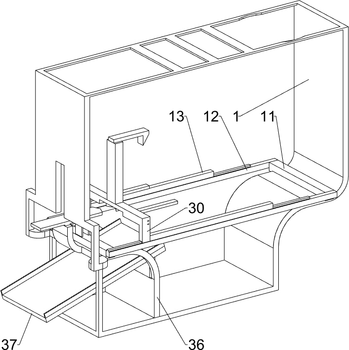
[0038] A bearing oiling device capable of preventing lubricating oil from overflowing, such as figure 1As shown, it includes a fixed frame 1, a grease container 2 and a bearing oiling mechanism 3. The grease container 2 is installed on the inner bottom of the fixed frame 1, and the bearing oiling mechanism 3 is installed on the inner top of the fixed frame 1. The bearing oiling mechanism 3 is located directly above the grease container 2.
[0039] When the bearing needs to be oiled, the user fixes the bearing through the bearing oiling mechanism 3, then the user adds an appropriate amount of grease to the grease container 2, and then the user moves the bearing downward through the bearing oiling mechanism 3, and the bearing moves downward The movement cooperates with the grease holder 2 to complete the oiling of the bearing. When the oiling of the bearing is completed, the user resets the bearing oiling mechanism 3, so that the bearing after oiling moves upwards away from the ...
Embodiment 2
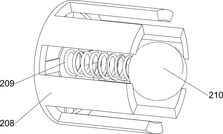
[0041] On the basis of Example 1, such as Figure 2-4 As shown, the grease holding part 2 includes a holding shell 201, a circular plate 202, a return spring 203, a hollow block 204, a sealing ring 205, a feeding pipe 207, a connecting frame 208, a first spring 209 and a sealing block 210 , the holding shell 201 is fixedly connected to the inner bottom of the fixed frame 1, and a circular plate 202 is slidably arranged in the holding shell 201, and a return spring 203 is fixedly connected between the bottom of the circular plate 202 and the inner bottom of the holding shell 201 The top of the circular plate 202 is evenly spaced with three hollow blocks 204, the top of the circular plate 202 inside the three hollow blocks 204 is embedded with a sealing ring 205, and the top of the circular plate 202 inside the sealing ring 205 has at least three outlets. Material hole 206, the lower part of the front side wall of the containing case 201 is embedded with a feed pipe 207, the low...
Embodiment 3
[0045] On the basis of Example 2, such as figure 1 , 8 As shown in -12, it also includes a mounting plate 4, a holding frame 5, a wedge-shaped sliding frame 6, an L-shaped plate 7, a fourth spring 8 and a feeding part, and the upper part of the right side wall in the fixed frame 1 is connected with a mounting plate 4 There is a holding frame 5 embedded between the mounting plate 4 and the fixed frame 1, the front and rear sides of the bottom of the mounting plate 4 are slidingly provided with a wedge-shaped sliding frame 6, and the front and rear side walls of the mounting plate 4 are all provided with L-shaped plates 7 A fourth spring 8 is fixedly connected between the adjacent L-shaped plate 7 and the wedge-shaped sliding frame 6 , and the fixed frame 1 on the lower side of the mounting plate 4 is provided with a feeding part, and the feeding part is located on the upper side of the holding shell 201 .
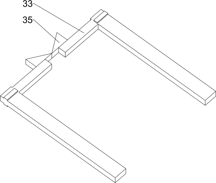
[0046] Such as Figure 9-12 As shown, the feeding part includes a mou...
PUM
 Abstract
Description
Claims
Application Information
 - R&D
- Intellectual Property
- Life Sciences
- Materials
- Tech Scout
- Unparalleled Data Quality
- Higher Quality Content
- 60% Fewer Hallucinations
Browse by: Latest US Patents, China's latest patents, Technical Efficacy Thesaurus, Application Domain, Technology Topic, Popular Technical Reports.
© 2025 PatSnap. All rights reserved.Legal|Privacy policy|Modern Slavery Act Transparency Statement|Sitemap|About US| Contact US: help@patsnap.com


