
Laser radar and control method thereof

A technology of laser radar and laser, which is applied in the direction of radio wave measurement systems and instruments, can solve problems such as device failure safety risks, and achieve the effect of low implementation complexity, high rationality, and high robustness

Pending Publication Date: 2021-10-19
HESAI TECH CO LTD
View PDF0 Cites 0 Cited by
  • Summary
  • Abstract
  • Description
  • Claims
  • Application Information

AI Technical Summary

Problems solved by technology

Therefore, there is an urgent need to solve the problem of safety risks caused by device failure when lidar is used as a key sensor for perception in automatic driving.

Method used


Image

  • Laser radar and control method thereof
  • Laser radar and control method thereof
  • Laser radar and control method thereof

Examples


Embodiment Construction

[0039] Hereinafter, some exemplary embodiments are simply described. As will be appreciated by those skilled in the art, the described embodiments can be modified in a variety of different ways without departing from the spirit or scope of the invention. Thus, the drawings and descriptions are considered to be exemplary rather than restrictive.

[0040] In the description of the present invention, it is necessary to understand that the term * # * center * # *, * # * portrait * # *, * # * horizontal * # *, * # * length * # *, * # * width * # *, * # * Thickness * # *, * # * on * # *, * # * *, * # * after * # *, * # * left * # * , * # * * # *, * # * Horizontal * # *, * # * top * # *, * # * bottom * # *, * # * within * # *, * # * Outside * # *, * # * Clock-clock * # *, * # * The orientation or positional relationship of the indication of the indication * # * is based on the orientation or positional relationship shown in the drawing, just for easy description Invention and simplificat...


PUM


Abstract

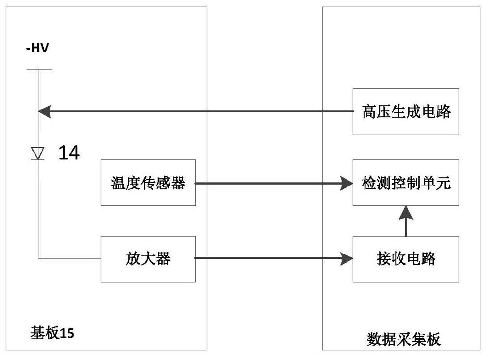
The invention provides a laser radar. The laser radar comprises a shell which is internally provided with an emitting cabin, a laser device assembly, aphotoelectric detector and adetection control unit, wherein the laser device assembly is arranged in the emitting bin, and the laser device assembly comprises a plurality of laser devices and is configured to be capable of emitting detection laser beams; the photoelectric detector is arranged in the emitting bin and is configured to receive stray light of the laser device and convert the stray light into an electric signal; and the detection control unit is coupled with the photoelectric detector and is configured to collect and analyze an electric signal of the photoelectric detector and judge whether the laser device assembly works normally or not according to an analysis result.

Description

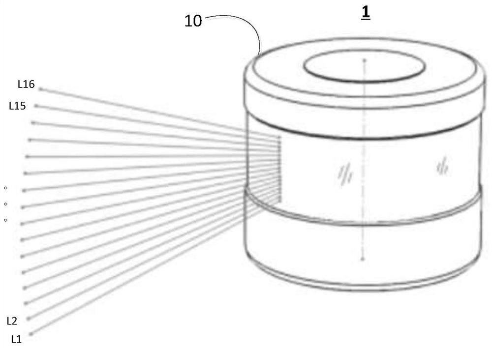
Technical field [0001] The present disclosure relates to the field of photoelectric technology, and more particularly to laser radar and a control method thereof. Background technique [0002] Laser radar Lidar is a collective as a laser active detection sensor device. The working principle is roughly as follows: laser radar transmits a bundle laser, after the laser beam encounters an object, returned to the laser receiver, radar module The distance between the transmitter and the object can be calculated based on the time interval of the transmission and reception signals. According to the laser harness, for example, there is, for example, a single laser radar, a 4-wire laser radar, 8 / 16 / 32 / 64 wire laser radar, and the like. One or more laser beams are transmitted along different angles in the vertical direction, scanned horizontally, and realizes the detection of three-dimensional profile of the target area. Multiple measurement channels (lines) are equivalent to the scanning p...

Claims


Application Information

Patent Timeline
Patent Type & Authority Applications(China)
IPC IPC(8): G01S7/497G01S7/481
CPCG01S7/497G01S7/481
Inventor 王力威于庆国赵鑫向少卿
Owner HESAI TECH CO LTD
Learn More