Combined type multipoint-distributed pressing device and free bending forming method for pipe
A pressing device and compound technology, applied in the directions of feeding device, positioning device, storage device, etc., can solve the problems of poor adaptability of pipe specifications and material strength, uneven application of pressing force, and obstruction of pipe feeding movement, etc. Achieve the effect of improving the forming ability and forming efficiency, solving the uneven application of pressing force, and solving the poor adaptability of material strength
- Summary
- Abstract
- Description
- Claims
- Application Information
AI Technical Summary
Problems solved by technology
Method used
Image
Examples
Embodiment 1
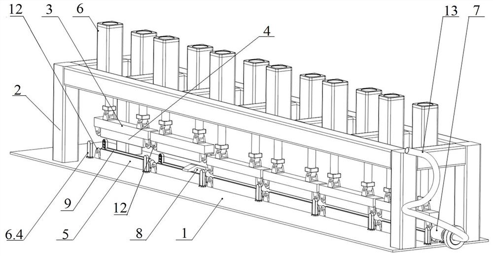
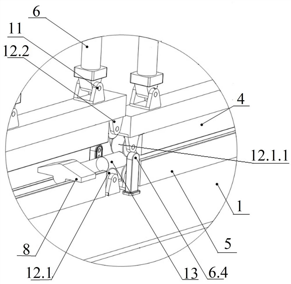
[0044] This embodiment discloses a composite multi-point distributed pressing device, as a basic implementation of the present invention, such as figure 1 As shown, including the fuselage frame and several pressing mechanisms, such as figure 1 with image 3 As shown, six pressing mechanisms can be set, and all the pressing mechanisms are arranged on the fuselage frame along the feeding direction of the pipe to form a multi-point distributed pressing condition.
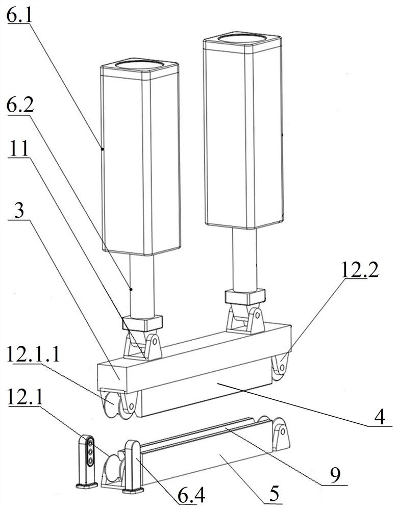
[0045] The fuselage frame is an important part of the supporting pressing mechanism, such as figure 1 As shown, a base 1 and a frame body 2 are included, and the frame body 2 is fixedly connected to the base 1 . The pressing mechanism comprises a mounting seat 3 , an upper pressing block 4 , a lower pressing block 5 , an upper pressing wheel set, a lower pressing wheel set and at least one pneumatic mechanism 6 . Wherein, the upper pressing block 4 is fixedly connected with the bottom of the mounting base 3 , and th...
Embodiment 2
[0047] In order to better realize the present invention, this embodiment discloses a preferred implementation, in order to further ensure the uniformity and effectiveness of the pressure applied to the pipe 13 to be formed, that is, in Example 1, as figure 2 As shown, the pressing mechanism is provided with two synchronously moving pneumatic mechanisms 6. Specifically, the top of the mounting seat 3 is provided with two hinges I11 at intervals along the pipe feeding direction, and the two hinges I11 are in the middle of the axis of the mounting seat 3. The distances between the points are equal, and the drive connecting rods 6.2 of the two pneumatic mechanisms 6 are detachably connected to the mounting base 3 through two hinges I11 respectively. Further, the upper pressing wheel set includes two pressing wheel assemblies 12 respectively located at both ends of the upper pressing block 4, and the lower pressing wheel set includes two pressing wheel assemblies 12 respectively lo...
Embodiment 3
[0049] In order to better realize the present invention, this embodiment discloses a preferred embodiment, that is, in Example 1, the upper compression block 4 and the lower compression block 5 are made of nylon material, and the friction coefficient of nylon material is small, and at the same time It has excellent mechanical strength and fatigue resistance, and is easy to process and replace. It can save production costs while ensuring the surface quality of formed pipes, and solves the problem of poor adaptability of material strength. Further, the pressure pipe groove 9 is a V-shaped groove. Compared with the pressure pipe groove 9 of other shapes (such as; if the pressure pipe groove 9 is arc-shaped, except for the pipe material 13 to be formed that is just the same as the diameter of the pressure pipe groove 9, Other pipes 13 to be formed are not applicable), the V-shaped groove is more versatile, applicable to various pipes 13 to be formed with different diameters, and ca...
PUM
 Abstract
Description
Claims
Application Information
 - R&D
- Intellectual Property
- Life Sciences
- Materials
- Tech Scout
- Unparalleled Data Quality
- Higher Quality Content
- 60% Fewer Hallucinations
Browse by: Latest US Patents, China's latest patents, Technical Efficacy Thesaurus, Application Domain, Technology Topic, Popular Technical Reports.
© 2025 PatSnap. All rights reserved.Legal|Privacy policy|Modern Slavery Act Transparency Statement|Sitemap|About US| Contact US: help@patsnap.com


