Construction equipment for forming wall base

A technology of construction equipment and base, which is applied in the field of construction equipment for forming wall bases, which can solve the problems of heavy weight, low precision and low work efficiency of base columns, and achieve increased friction, high work efficiency and high precision , It is convenient for accurate laying and docking effect

Pending Publication Date: 2021-10-22
吴智鹏
View PDF10 Cites 0 Cited by
  • Summary
  • Abstract
  • Description
  • Claims
  • Application Information

AI Technical Summary

Problems solved by technology

[0004] The base needs to accurately dock the base column on the tubular member, and the base column has a hu

Method used


Image

  • Construction equipment for forming wall base
  • Construction equipment for forming wall base
  • Construction equipment for forming wall base

Examples


Embodiment Construction

[0052] The following description serves to disclose the present invention to enable those skilled in the art to carry out the present invention. The preferred embodiments described below are only examples, and those skilled in the art can devise other obvious variations.

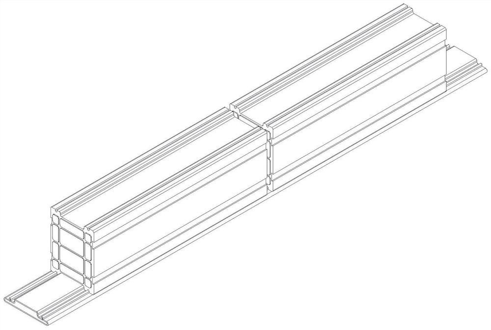
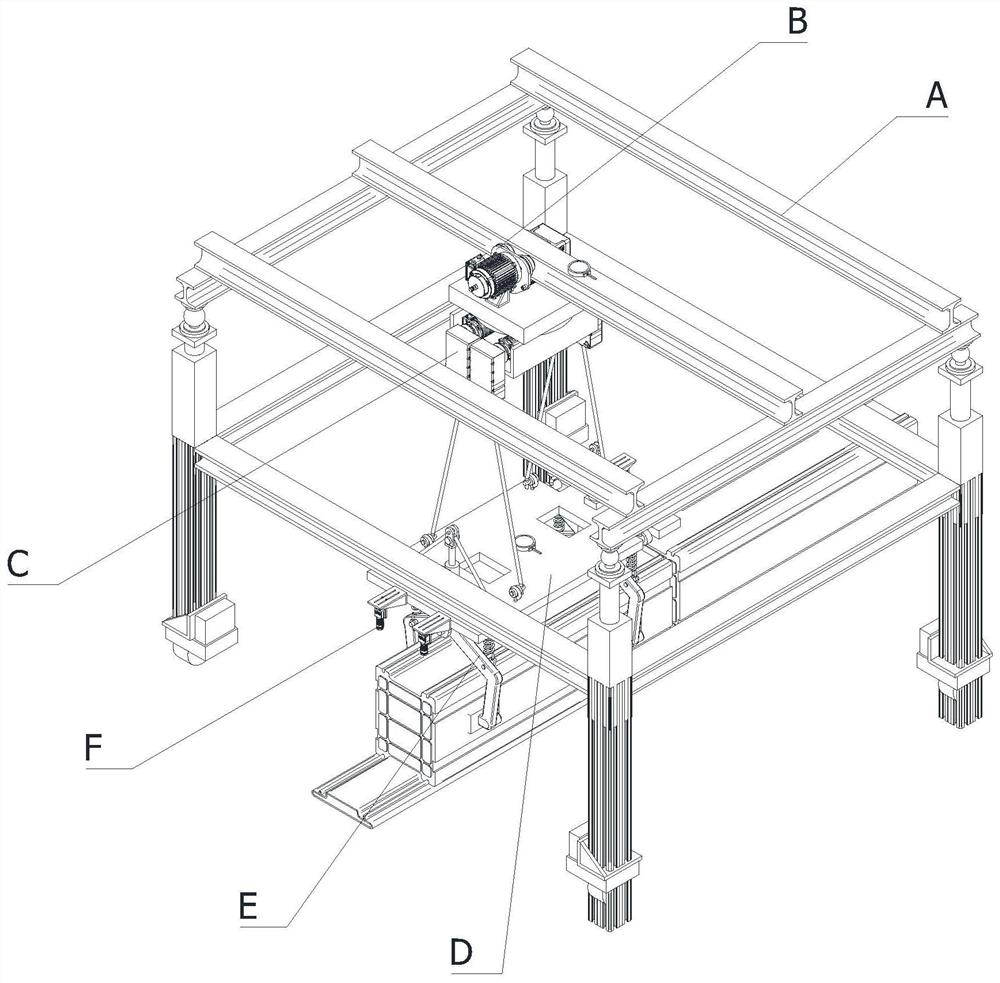
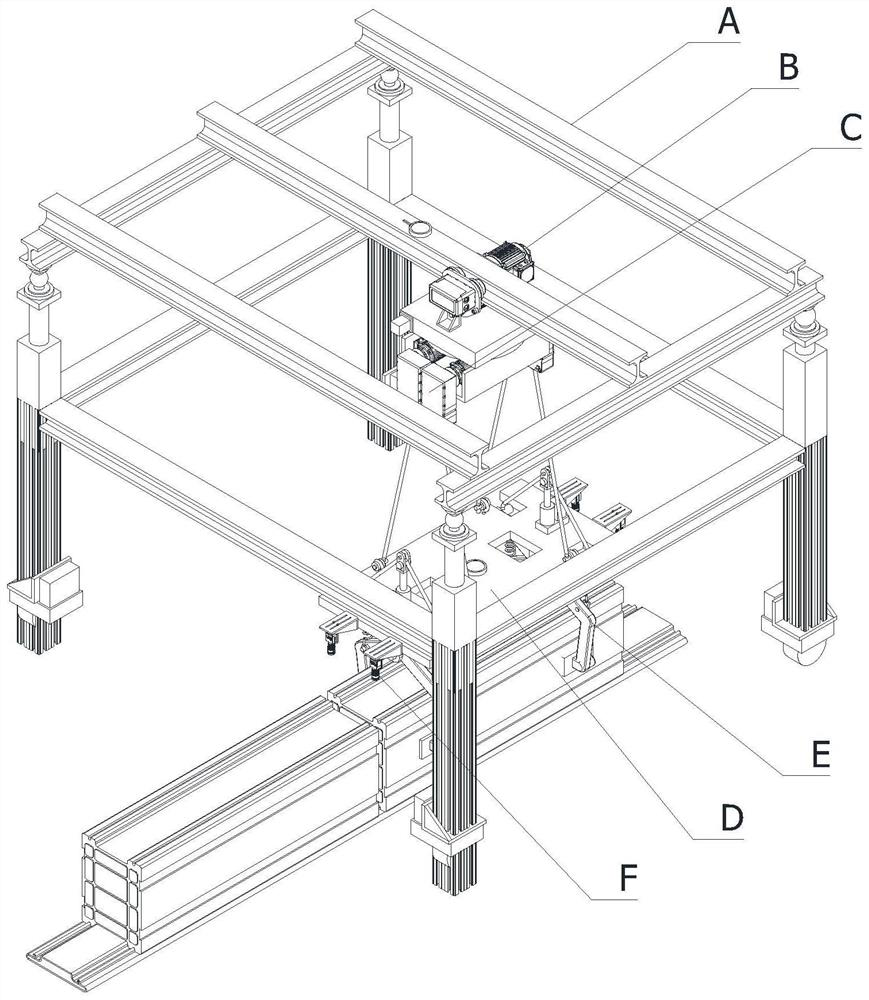
[0053] In order to solve the technical problem of being able to automatically and accurately place the base column on the tubular member, such as figure 1 , figure 2 and image 3 As shown, the following technical solutions are provided:

[0054] A construction device for forming a wall base, characterized in that it includes,

[0055] A traveling mechanism A, which is used to move along the laying direction on the top of the tubular member;

[0056] A sliding mechanism B, the sliding mechanism B is arranged on the top of the running mechanism A along the horizontal direction, and the sliding mechanism B includes a working end that can move horizontally on the top of the running mechanism A;

[0057] A ...


PUM


Abstract

The invention relates to the field of building construction, in particular to construction equipment for forming a wall base. The construction equipment comprises a traveling mechanism, a sliding mechanism, a traction mechanism, a lifting plate, a clamping mechanism and industrial cameras, wherein the traveling mechanism is used for moving at the top of a tubular component along a laying direction; the sliding mechanism is arranged at the top of the traveling mechanism in the horizontal direction, and the sliding mechanism comprises a working end capable of horizontally moving at the top of the traveling mechanism; the traction mechanism is arranged at the working end of the sliding mechanism, and the traction mechanism comprises a traction point capable of ascending and descending in the vertical direction; the lifting plate is horizontally arranged at the top of the traction mechanism, and the top of the lifting plate is fixedly connected with a traction point of the traction mechanism; the clamping mechanism is arranged on the lifting plate, and a clamping opening of the clamping mechanism is vertically downward and is located at the bottom of the lifting plate; and the industrial cameras are arranged on the two sides of the clamping mechanism, and the clamping mechanism is used for observing the joint positions of the adjacent base foot columns in the vertical direction. According to the construction equipment, the working efficiency and precision are high.

Description

technical field [0001] The invention relates to the field of building construction, in particular to a construction device for forming a wall base. Background technique [0002] The wall base refers to the load-bearing member that the bottom of the building is in contact with the foundation. Its function generally refers to transferring the load from the upper part of the building to the foundation. So the foundation must be strong, stable and reliable. Part of the structural components below the ground of engineering structures is used to transmit the superstructure load to the foundation, and is an important part of houses, bridges, docks and other structures. Whereas in the field concerned with the construction of temporary or permanent buildings with light structures, i.e. reinforced concrete foundations produced in the prior art, the elevated height of the building is usually achieved by using angle brackets or flat Partly constrained to the reinforced concrete founda...

Claims


Application Information

Patent Timeline
IPC IPC(8): E04G21/16E04G21/18
CPCE04G21/16E04G21/162E04G21/18E04G21/1841Y02E10/20
Inventor 吴智鹏
Owner 吴智鹏
Why Eureka
Try Eureka