
Control valve, control oil way and variable compression ratio engine

A technology for controlling oil circuits and control valves, which is applied in engine control, machines/engines, mechanical equipment, etc. It can solve problems such as high processing and production costs, increased oil circuits, and complex structures, and achieve compact overall structure and reduced layout space the effect of the requirements

Active Publication Date: 2021-10-22
GUANGZHOU AUTOMOBILE GROUP CO LTD
View PDF6 Cites 0 Cited by
  • Summary
  • Abstract
  • Description
  • Claims
  • Application Information

AI Technical Summary

Problems solved by technology

At present, there are mainly two kinds of connecting rod devices that realize variable compression ratio. One is to use a mechanical valve as the switching control valve of the compression ratio, which requires a motor and a mechanical rod to trigger the switching control valve. The connecting rod of the actuator has many oil circuits. The layout space requirements are high; the other is to use the spring valve as the switching control valve of the compression ratio, but in order for the oil body in the high and low hydraulic chamber of the connecting rod to return to the oil supply chamber of the crankshaft connecting rod, it is necessary to add multiple control valves. Valves also lead to an increase in the number of oil circuits arranged, and the requirements for the layout space are also high. The control valves and corresponding control oil circuits used in the above two methods all have the disadvantages of complex structure, high requirements for space layout, and high processing and production costs.

Method used


Image

  • Control valve, control oil way and variable compression ratio engine
  • Control valve, control oil way and variable compression ratio engine
  • Control valve, control oil way and variable compression ratio engine

Examples


Embodiment Construction

[0031] The specific implementation manners of the present invention will be further described in detail below in conjunction with the accompanying drawings and embodiments. The following examples are used to illustrate the present invention, but are not intended to limit the scope of the present invention.

[0032] In the description of the present invention, it should be noted that the terms "upper", "lower", "front", "rear", "left", "right", "vertical", "horizontal", "top", The orientation or positional relationship indicated by "bottom", "inner", "outer", etc. is based on the orientation or positional relationship shown in the drawings, and is only for the convenience of describing the present invention and simplifying the description, rather than indicating or implying the referred device or positional relationship. Elements must have certain orientations, be constructed and operate in certain orientations, and therefore should not be construed as limitations on the invent...


PUM


Abstract

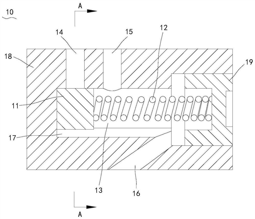
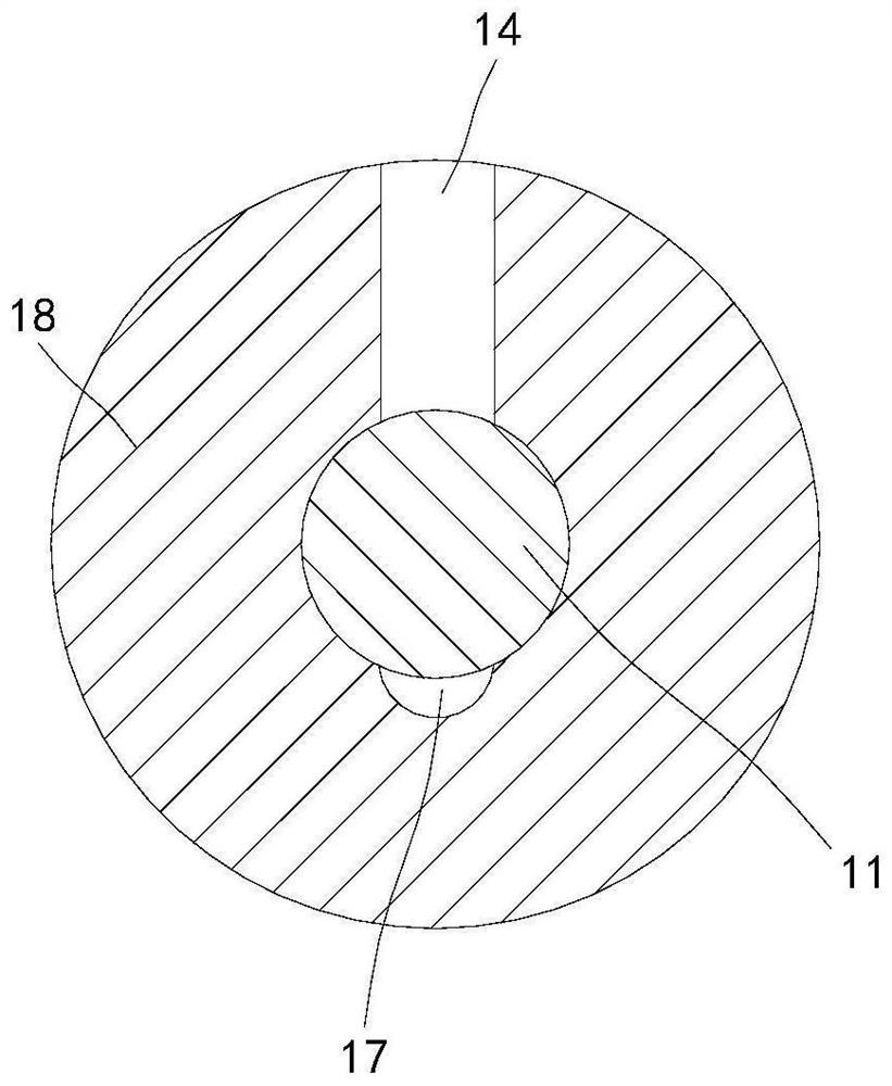
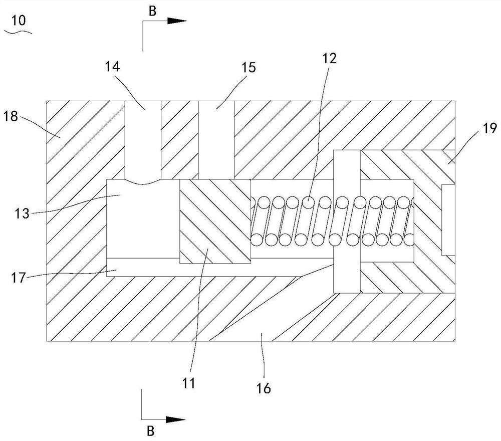
The invention relates to the technical field of engines, and discloses a control valve, a control oil way and a variable compression ratio engine comprising the control oil way. The control valve comprises a valve body, a valve element and an elastic piece, a valve cavity is formed in the valve body, and the valve element is connected to the first end of the valve cavity through the elastic piece; the valve body is provided with a first inlet, a second inlet and a backflow opening which are communicated with the valve cavity, a backflow groove communicates with the backflow opening, the control valve is applied to the control oil way of the variable compression ratio engine, backflow channels can be switched in the single control valve, the automatic oil charging and discharging functions of two hydraulic cavities of a connecting rod control oil way are achieved. Excessive oil ways do not need to be arranged, the requirement for arrangement space is reduced, the compression ratio of the engine is changed by controlling the length of an oil way switching connecting rod, and the overall structure of the engine is made to be compact.

Description

technical field [0001] The invention relates to the technical field of engines, in particular to a control valve, a control oil passage and a variable compression ratio engine including the same. Background technique [0002] Variable compression ratio technology is a revolutionary technology in the development of engines. Using high compression ratio at low load in the engine can improve the thermal efficiency of the engine and reduce fuel consumption. Using low compression ratio at high load can increase the power and torque of the engine to meet the power requirements. . At present, there are mainly two kinds of connecting rod devices that realize variable compression ratio. One is to use a mechanical valve as the switching control valve of the compression ratio, which requires a motor and a mechanical rod to trigger the switching control valve. The connecting rod of the actuator has many oil circuits. The layout space requirements are high; the other is to use the sprin...

Claims


Application Information

Patent Timeline
IPC IPC(8): F02D15/02F02B75/04
CPCF02D15/02F02B75/045
Inventor 罗海鹏吴琪占文锋易敬华
Owner GUANGZHOU AUTOMOBILE GROUP CO LTD
Learn More