
Oil separator, compressor assembly and heat exchange equipment

A technology of oil separator and compressor, which is applied in the field of oil separation, can solve problems such as difficulty in meeting compressor performance requirements, large gas pressure loss, and compressor performance loss, so as to improve oil separation effect, reduce flow resistance, and reduce The effect of oil output

Pending Publication Date: 2021-10-22
GUANGDONG MIDEA WHITE GOODS TECH INNOVATION CENT CO LTD +1
View PDF0 Cites 0 Cited by
  • Summary
  • Abstract
  • Description
  • Claims
  • Application Information

AI Technical Summary

Problems solved by technology

As for the compressor with direct discharge in the cylinder, that is, there is one way that the refrigerant of the cylinder is directly discharged from the compressor, which will cause too much oil discharge; , but the pressure loss of the gas is large, so the performance loss of the compressor is serious, and the conventional oil separator cannot guarantee the oil discharge rate, and it is difficult to meet the performance requirements of the compressor

Method used


Image

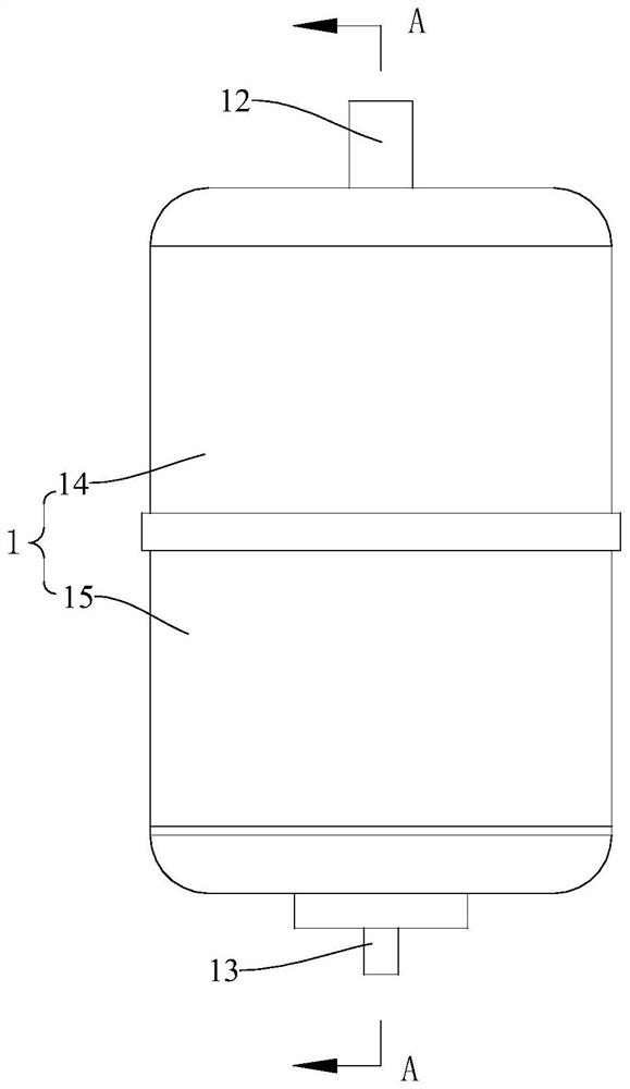
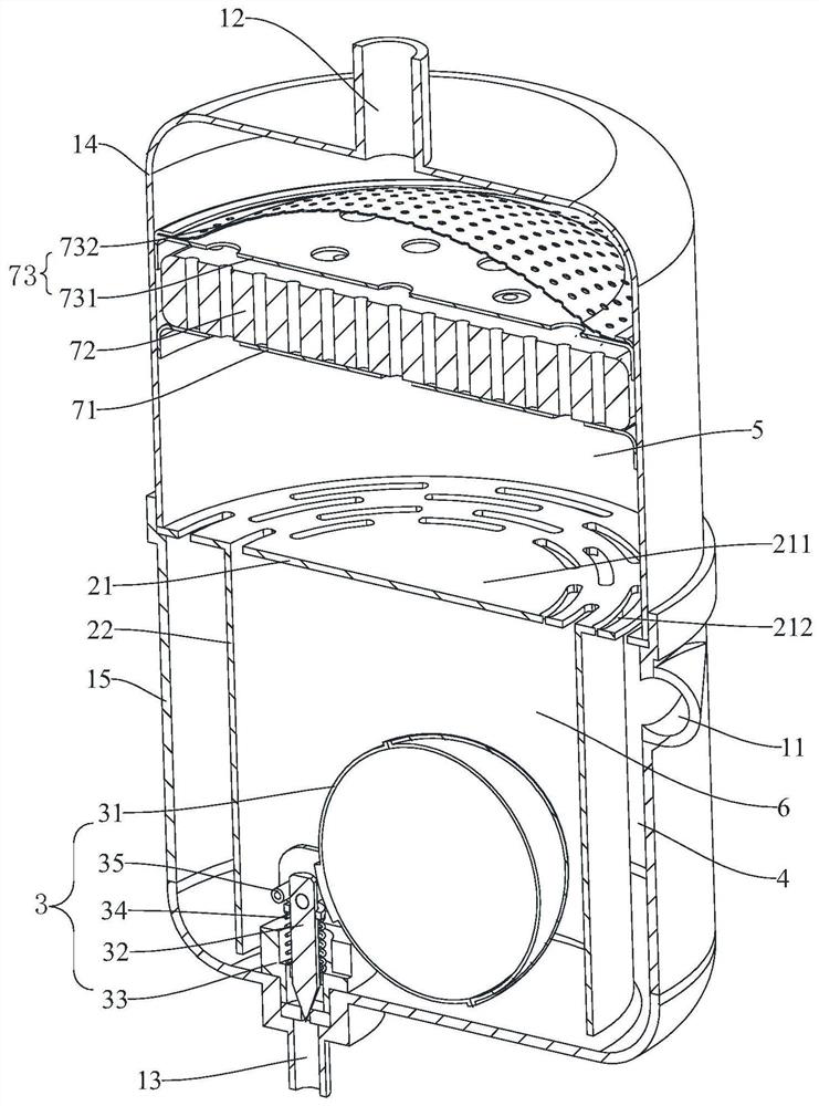
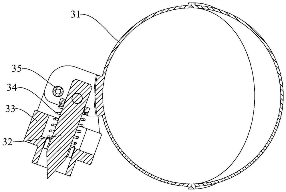
  • Oil separator, compressor assembly and heat exchange equipment
  • Oil separator, compressor assembly and heat exchange equipment
  • Oil separator, compressor assembly and heat exchange equipment

Examples


Embodiment Construction

[0051] Embodiments of the present invention will be further described in detail below in conjunction with the accompanying drawings and examples. The following examples are used to illustrate the present invention, but should not be used to limit the scope of the present invention.

[0052] In the description of the embodiments of the present invention, it should be noted that the orientations or positional relationships indicated by the terms "upper", "lower", "top", "bottom", "inner" and "outer" are based on the drawings The orientation or positional relationship shown is only for the convenience of describing the embodiment of the present invention and simplifying the description, and does not indicate or imply that the referred device or element must have a specific orientation, be constructed and operated in a specific orientation, and therefore cannot be understood as Restrictions on the embodiments of the present invention. In addition, the terms "first" and "second" ar...


PUM


Abstract

The invention relates to the technical field of oil separation, and provides an oil separator, a compressor assembly and heat exchange equipment. The oil separator comprises a shell, a partition component and an oil discharge component, and the shell is provided with an air inlet structure, an air exhaust structure and an oil discharge structure; the partition component is arranged in the shell and divides the shell into a first separation area, a second separation area and an oil return area which are communicated with one another, the air inlet structure is arranged in the tangential direction of the shell corresponding to the first separation area, the air inlet structure communicates with the first separation area. The air exhaust structure correspondingly communicates with the second separation area; the oil discharge component is arranged in the oil return area and used for adjusting connection and disconnection of the oil discharge structure and the oil return area. According to the oil separator, the compressor assembly and the heat exchange equipment, the flowing resistance of gas is reduced, the oil separation effect is improved, the oil spitting amount is reduced, and the oil discharge precision can be improved.

Description

technical field [0001] The invention relates to the technical field of oil separation, in particular to an oil separator, a compressor assembly and heat exchange equipment. Background technique [0002] The oil separator can separate the lubricating oil in the high-pressure gas discharged from the compressor to ensure the safe and efficient operation of the heat exchange system. The exhaust port of the compressor has a certain amount of oil discharge. For conventional single exhaust compressors, the gas needs to pass through structures such as motors and oil baffles. The structures such as motors and oil baffles are helpful for gas oil separation. The oil discharge rate is relatively low, which can generally meet the operating requirements of the compressor. As for the compressor with direct discharge in the cylinder, that is, there is one way that the refrigerant of the cylinder is directly discharged from the compressor, which will cause too much oil discharge; , but the...

Claims


Application Information

Patent Timeline
IPC IPC(8): F04B39/04B01D50/00
CPCF04B39/04
Inventor 方文杰高科科张肃李志林
Owner GUANGDONG MIDEA WHITE GOODS TECH INNOVATION CENT CO LTD
Learn More