An Integral Design Method of Multilayer Rod-end Spherical Joint

A design method and technology of ball joints, applied in the direction of mechanical equipment, shafts, bearings, pivots, etc., can solve the problems of easy wrinkling and fracture of the rubber layer, low service life of ball joints, and small radial rigidity, so as to avoid rubber wrinkles and fractures , Reduce the difficulty of processing technology, increase the effect of radial stiffness

Active Publication Date: 2022-03-18
ZHUZHOU TIMES NEW MATERIALS TECH
View PDF14 Cites 0 Cited by
  • Summary
  • Abstract
  • Description
  • Claims
  • Application Information

AI Technical Summary

Problems solved by technology

At present, the rod end ball joint generally adopts the form of pure metal joint or the form of single-layer rubber joint of metal jacket-single-layer rubber layer-metal inner sleeve; the form of pure metal joint has poor environmental adaptability, especially in sandy and dusty environments, which is prone to wear and tear. There are often large areas of abnormal noise during the application process, and the abnormal noise problem cannot be improved by improving the metal joint, which leads to a reduction in the service life of the metal joint, and the price of the pure metal joint is high; the metal jacket-single rubber layer-metal inner sleeve Rod end ball joints in the form of single-layer rubber joints have small radial stiffness, can only bear small radial stiffness, and have poor resistance to deflection torsional loads. The rubber layer is easy to wrinkle and break during use, resulting in a low service life of the ball joint.

Method used


Image

  • An Integral Design Method of Multilayer Rod-end Spherical Joint
  • An Integral Design Method of Multilayer Rod-end Spherical Joint
  • An Integral Design Method of Multilayer Rod-end Spherical Joint

Examples


Embodiment 1

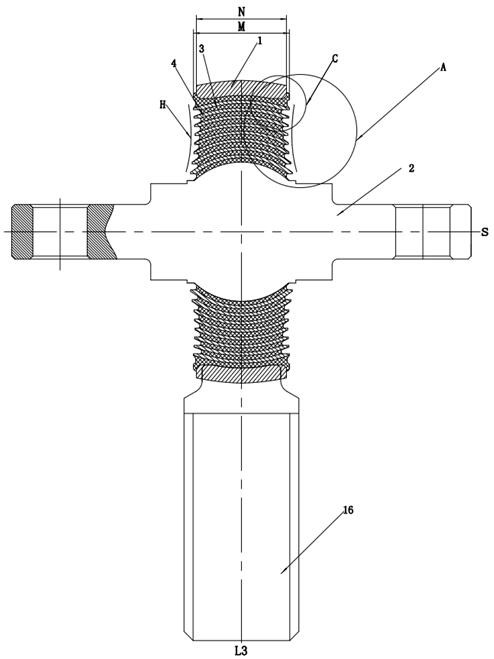
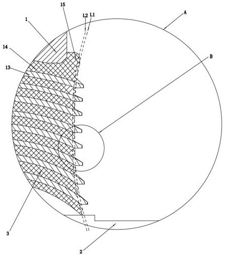
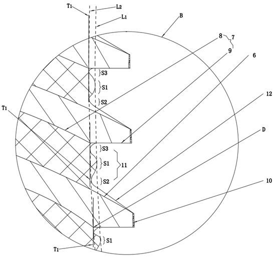
[0052] as attached Figure 1-9 As shown, an overall design method of a multi-layer rod-end ball joint, the above-mentioned rod-end ball joint includes an outer casing 1, a mandrel 2 and a rubber layer 3, and a plurality of spacers 4 are arranged in the rubber layer 3, and the adjacent spacers The rubber profile between 4 is combined with the spacer 4 to form a concave anti-stretch unit, such as image 3 As shown, the anti-stretch unit includes a concave bottom surface 11, a first outer surface 12 located on the lower side of the concave bottom surface 11 and facing the outside of the ball joint, and a second outer surface 9 located on the upper side of the concave bottom surface 11 and facing the outside of the ball hinge. The bottom surface 11 is set as a rubber profile structure composed of multi-arc sections to improve the tensile performance of the rubber layer 3 of the ball joint, prevent the rubber layer 3 from wrinkling and breaking when the ball joint is subjected to a...

Embodiment 2

[0081] This example is attached Figure 10 and Figure 11 As shown, the difference between Embodiment 2 and Embodiment 1 is that the end face 5 of the spacer is arranged obliquely from the outer end of the upper side 6 of the spacer toward the inner side of the ball joint, and the intersection of the upper side 6 of the spacer and the end face 5 of the spacer is formed. Tip E, using tip E to make point contact with the mold for axial positioning of the spacer during vulcanization. Setting the spacer sleeve end surface 5 from the outer end of the spacer sleeve upper side 6 towards the inner side of the ball joint can make the positioning of the spacer sleeve 4 more stable in the mould. , which further reduces the difficulty of processing the ball joint before vulcanization.

Embodiment 3

[0083] as attached Figure 12 As shown, the difference between the present embodiment and the second embodiment is that several narrow and long small grooves 33 are arranged at the groove bottom of the curved surface groove 25. The groove 33 further increases the bonding area between the outer layer spacer 13 and the outer layer 1 to prevent the outer rubber 13 from peeling off from the outer layer 1 and the outer layer spacer 13 when the ball joint is subjected to a large torsional load, thereby increasing the strength of the ball joint. service life.


PUM


Abstract

The invention relates to the technical field of shock absorption of elastic rubber parts, in particular to an overall design method of a multi-layer rod-end ball joint. Performance, specifically to improve the service life of the ball joint through the design of the rubber profile; to improve the service life of the ball joint or reduce the processing difficulty of the ball joint before vulcanization through the design of the spacer sleeve; to reduce the The difficulty of processing the ball joint before vulcanization may improve the service life of the ball joint.

Description

technical field [0001] The invention relates to the technical field of shock absorption of elastic rubber parts, in particular to an overall design method of a multi-layer rod-end ball joint. Background technique [0002] The rod end ball joint is an important shock-absorbing connection element, which is mostly used in trains, high-speed rail, automobiles, ships or airplanes. When the body is subjected to complex load conditions such as radial, torsion and deflection, the deformation of the rod end ball joint is used to bear Deviated torsion angle and radial load to prevent the body from rolling over during operation. At present, the rod end ball joint generally adopts the form of pure metal joint or the form of single-layer rubber joint of metal jacket-single-layer rubber layer-metal inner sleeve; the form of pure metal joint has poor environmental adaptability, especially in sandy and dusty environments, which is prone to wear and tear. There are often large areas of abno...

Claims


Application Information

Patent Timeline
Patent Type & Authority Patents(China)
IPC IPC(8): F16C11/06F16F15/08
CPCF16C11/06F16C11/0695F16F15/08
Inventor 杨军冯万盛黄江彪谭方曹政
Owner ZHUZHOU TIMES NEW MATERIALS TECH
Why Eureka
Try Eureka