Method for determining sealing clearance of labyrinth honeycomb structure in working state

A working state and honeycomb structure technology, applied in the field of aero-engines, can solve the problem of inaccurate sealing gap measurement and achieve accurate measurement results

Pending Publication Date: 2021-10-22
AECC SHENYANG ENGINE RES INST
View PDF11 Cites 0 Cited by
  • Summary
  • Abstract
  • Description
  • Claims
  • Application Information

AI Technical Summary

Problems solved by technology

[0008] The purpose of this application is to provide a method for determining the sealing gap in the working state of the comb tooth honeycomb structure, so as to solve the technical effect of the inaccurate measurement of the sealing gap in the prior art

Method used


Image

  • Method for determining sealing clearance of labyrinth honeycomb structure in working state
  • Method for determining sealing clearance of labyrinth honeycomb structure in working state
  • Method for determining sealing clearance of labyrinth honeycomb structure in working state

Examples


Embodiment 1

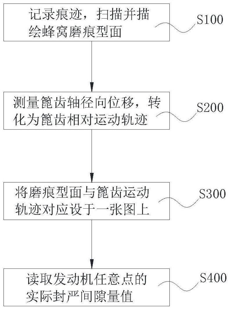
[0029] Embodiment 1, a method for determining the sealing gap in the working state of the comb tooth honeycomb structure, such as figure 1 shown, including:

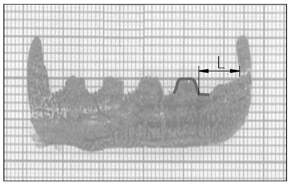
[0030] Such as figure 2 As shown, step S100, record the existing traces, print on the coordinate paper and scan the records, and describe the honeycomb wear trace profile 7;

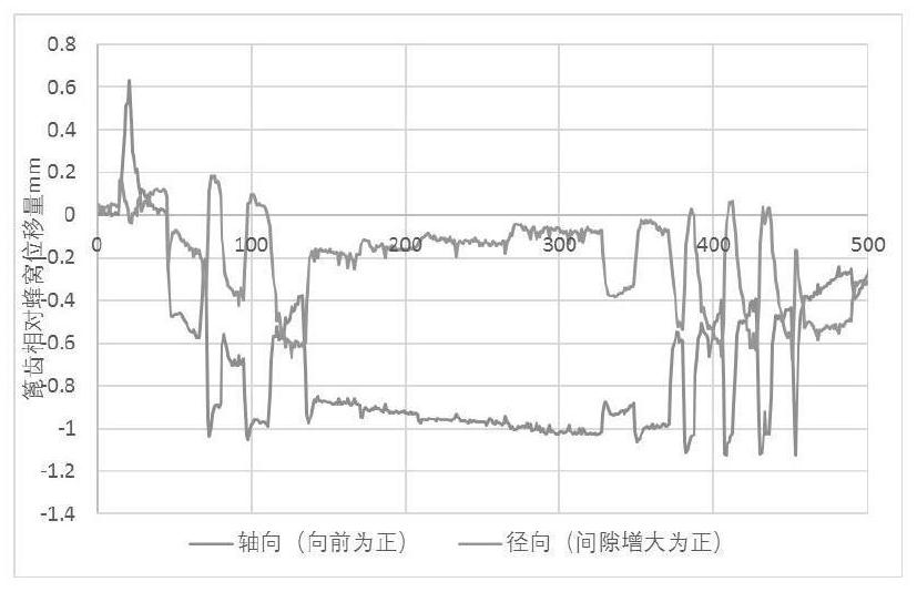
[0031] Such as image 3 , 4 As shown, in step S200, measure the axial and radial relative displacement of the grate honeycomb, and convert it into the relative motion track 5 of the grate;

[0032] Such as Figure 5 As shown, in step S300, the honeycomb wear scar profile 7 and the trajectory of the grate teeth are correspondingly arranged on a map;

[0033] Step S400, reading the actual sealing gap value at any point in the entire working process of the engine.

[0034] Since the honeycomb wear marks are set on the stator, when measuring the actual sealing gap value at a certain point, the axial position also changes accordingly, and the axi...

Embodiment 2

[0042] Embodiment 2, as a specific implementation, also includes a system for determining the sealing gap in the working state of the comb tooth honeycomb structure, such as Figure 5 , 6 As shown, it includes a honeycomb wear trace recording module 1, a grate track forming module 2, a trace corresponding module 3, and a gap measurement module 4.

[0043] The honeycomb wear scar recording module 1 is used to scan and record the wear traces, and describe the honeycomb wear scar profile 7;

[0044] The grate tooth trajectory forming module 2 is used to measure the relative displacement of the grate tooth honeycomb and convert it into the relative motion trajectory 5 of the grate tooth;

[0045] The trace corresponding module 3 is used to set and save the honeycomb wear trace profile 7 and the relative motion trajectory 5 of the grate tooth on a map;

[0046] The gap measurement module 4 is used to measure the actual sealing gap value between the rotor and the casing.

[0047]...

Embodiment 3

[0051] Embodiment 3, as a specific implementation, also includes an aero-engine, including the system for determining the sealing gap as described in Embodiment 2, which can accurately determine the sealing gap of the grate teeth in any state within the entire operating speed range.


PUM


Abstract

The invention relates to the field of aero-engines, in particular to a method for determining the sealing clearance of a labyrinth honeycomb structure in a working state. The method comprises the steps that existing abrasion marks are recorded and printed on coordinate paper, and a honeycomb abrasion mark molded surface is scanned, recorded and described; the axial and radial relative displacements of a labyrinth honeycomb are measured and converted into a labyrinth relative movement track; the honeycomb abrasion cracks and the labyrinth movement track are correspondingly arranged on a graph and stored; and the actual sealing clearance value of any point in the whole working process of the engine is read. The actual sealing clearance value of any point can be accurately obtained.

Description

technical field [0001] The application belongs to the field of aero-engines, and in particular relates to a method for determining a sealing gap in a working state of a grate honeycomb structure. Background technique [0002] Grate honeycomb seal belongs to non-contact dynamic seal, and is an effective and long-life sealing structure widely used in rotating machinery such as aero-engines. Generally, the allowable contact friction on the sealing ring is designed to be abradable, such as coating, metal honeycomb and brush lining, etc. Accurately grasping the sealing gap has an important impact on the calculation of leakage and overall machine performance. However, in the actual operation of the engine, the rotor and the stator not only have radial deformation, but due to the existence of honeycomb wear marks, the axial deformation of the rotor affects the actual sealing gap in the radial direction, making it difficult to determine the sealing gap in the actual work of the comb...

Claims


Application Information

Patent Timeline
IPC IPC(8): G01B15/00
CPCG01B15/00
Inventor 梁爽黄耀宇张淑奎
Owner AECC SHENYANG ENGINE RES INST
Why Eureka
Try Eureka