Water leakage detection equipment for water conveying pipeline

A technology for water delivery pipelines and testing equipment, applied in mechanical equipment, pipeline systems, and other directions by detecting the appearance of fluid at the leak point, can solve problems such as easy shaking of testing equipment, and achieve the effect of reducing impact and preventing noise problems.

Pending Publication Date: 2021-10-22
BEIJING JOYO SMART WATER METER
View PDF0 Cites 0 Cited by
  • Summary
  • Abstract
  • Description
  • Claims
  • Application Information

AI Technical Summary

Problems solved by technology

[0004] The purpose of the present invention is to provide water leakage detection equipment for water pipelines to solve the technical problem that the detection equipment in the prior art is easy to shake during the detection process

Method used


Image

  • Water leakage detection equipment for water conveying pipeline
  • Water leakage detection equipment for water conveying pipeline
  • Water leakage detection equipment for water conveying pipeline

Examples


Embodiment 1

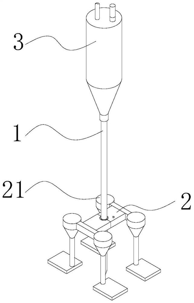
[0064] The invention provides a water leakage detection device for water pipelines. The overall structure of the device is as follows: figure 1 As shown, it includes an acoustic cavity 3, a listening rod 1 and a first limiting device 2, wherein the first limiting device 2 includes a limiting plate and a support member 21, and the limiting plate is composed of a first supporting plate 23 and a second The support plate 24 is formed, and a limiting hole 22 structure for fixing the listening rod 1 and allowing the listening rod 1 to move relatively is formed at the contact surface of the two.

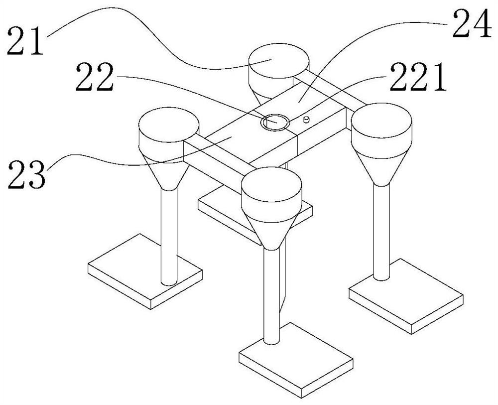
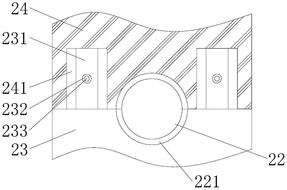
[0065] Specifically, the structure of the above-mentioned first limiting device 2 is as follows: figure 2 and image 3 As shown, the first support plate 23 is fixedly provided with a positioning rod 231 toward the side of the second support plate 24, and the corresponding position of the second support plate 24 is provided with a positioning groove 241 that can be used in conjunction with...

Embodiment 2

[0081] The difference between this embodiment 2 and embodiment 1 is that the fixing structure does not include the matching block 432 structure at this time, and the two ends of the spring 433 sleeved on the matching rod 434 are connected with the inner side wall of the housing 42 and the supporting rod 431 respectively. fixed connection, such as Figure 8 shown.

[0082] When the pull rod 44 moves up and down through the movable hole 422 , the adjustment rod 452 can drive the fixed rod 435 and the support rod 431 to squeeze the spring 433 to adjust the connection relationship between the fixed rod 435 and the limit rod 41 .


PUM


Abstract

The invention provides water leakage detection equipment for a water conveying pipeline, relates to the technical field of water leakage detection, and mainly aims to solve the problems that traditional sound listening detection equipment is easy to shake during use, and the detection accuracy is influenced. The water leakage detection equipment for the water conveying pipeline comprises a listening rod and a first limiting device, the first limiting device comprises a limiting plate and a supporting piece located below the limiting plate, and a distance exists between the limiting plate and the ground under the supporting of the supporting piece; a limiting hole is formed in the upper surface and the lower surface of the limiting plate in a penetrating mode, and when the listening rod is arranged on the limiting hole in a penetrating mode, the outer wall of the listening rod is connected with the inner wall of the limiting hole in an attached mode, and the listening rod can slide relative to the limiting hole in the axis direction of the listening rod. The equipment further comprises a sound cavity, a second limiting device is fixedly arranged in the sound cavity, and the upper end of the stethoscope rod is fixedly arranged in the sound cavity through the second limiting device. The problem that noise is easily generated in the listening rod detection process is solved by limiting the listening rod.

Description

technical field [0001] The invention relates to the technical field of water leakage detection, in particular to a water leakage detection device for water pipelines. Background technique [0002] The water supply pipe network is the material basis for the city's survival and development. Due to the widespread aging of the pipe network and the impact of construction, the leakage of the pipe network is serious. The leakage of the pipe network not only causes a waste of resources, but also increases disasters, processing costs and For the maintenance cost of related facilities, the commonly used methods for detecting pipe networks include conventional audio-audio method, correlation analysis method, regional leak detection method, regional meter installation method, and regional leak detection method and regional meter installation method, among which the conventional audio-audio method is the main method. To sum up, the problem existing in the prior art is that the audio-audi...

Claims


Application Information

Patent Timeline
Patent Type & Authority Applications(China)
IPC IPC(8): G01M3/02G01M3/24F17D5/06F16M7/00
CPCG01M3/02G01M3/243F17D5/06F16M7/00
Inventor 毕建光
Owner BEIJING JOYO SMART WATER METER
Why Eureka
Try Eureka