Voltameter circuit, control method, voltameter and terminal
A technology of electricity metering and electricity meter, which is applied in the direction of measuring electric variables, measuring devices, instruments, etc., can solve the problem that the electricity meter circuit cannot adapt to current changes, and achieve the effect of avoiding heat loss and burning out devices
- Summary
- Abstract
- Description
- Claims
- Application Information
AI Technical Summary
Problems solved by technology
Method used
Image
Examples
Embodiment 1
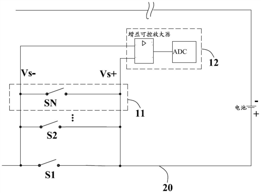
[0040] see figure 2 , shows the fuel gauge circuit in the first embodiment of the present invention, which is connected to the charging and discharging circuit 20 of the terminal, and is used to measure the charging and discharging power. The fuel gauge circuit includes a current detection circuit and is connected to the current detection circuit The power metering module 12, wherein:
[0041] The current detection circuit is connected in series on the charging and discharging circuit 20, the current detection circuit includes a plurality of current detection branches 11, and the plurality of current detection branches 11 are connected in parallel with each other, the current detection branch 11 includes a first controllable switch, and a plurality of first The controllable switches are respectively S1~SN (N>=2). When any first controllable switch is closed, the corresponding current detection branch 11 is turned on, thereby turning on the charging and discharging circuit 20....
Embodiment 2
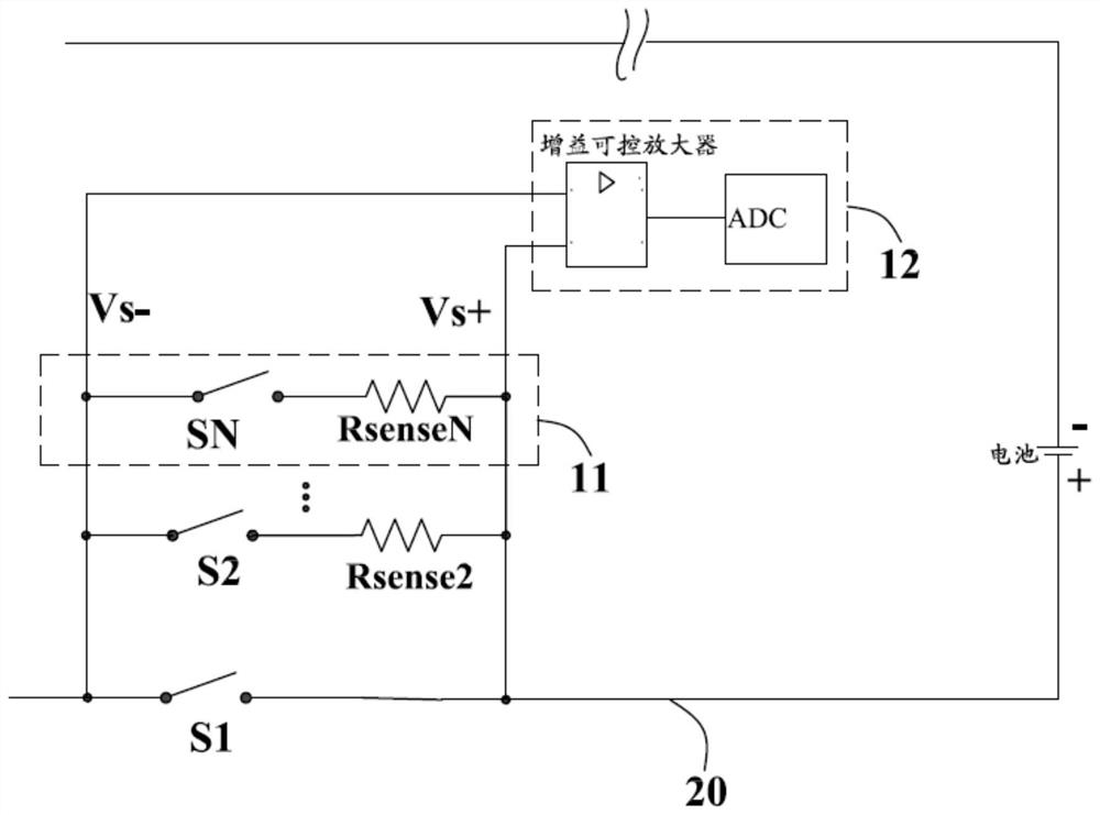
[0054] see image 3 , shows the fuel gauge circuit in the second embodiment of the present invention, the difference between the fuel gauge circuit in this embodiment and the fuel gauge circuit in the first embodiment is:
[0055] At least one current detection branch 11 also includes a current detection resistor connected in series with the first controllable switch on the current detection branch, and the two input terminals of the gain controllable amplifier are respectively connected to both ends of the current detection branch. The potential at both ends of the current-sensing branch is used as the differential input of the gain controllable amplifier. In some optional embodiments of this embodiment, such as image 3 As shown, except for the current-sensing branch where the first controllable switch S1 is located, the other current-sensing branches include current-sensing resistors, and the multiple current-sensing resistors are respectively Rsense2˜RsenseN (N>=2). That...
Embodiment 3
[0060] see Figure 4 , shows the fuel gauge circuit in the third embodiment of the present invention, the difference between the fuel gauge circuit in this embodiment and the fuel gauge circuit in the second embodiment is:
[0061] Each current detection branch includes a current detection resistor, and the two input terminals of the gain controllable amplifier are respectively connected to both ends of the current detection resistor, so that the potential at both ends of the current detection resistor is used as a differential input of the gain controllable amplifier. That is, in this embodiment, the current-sensing resistor is solely used as the current-sensing impedance of the current-sensing branch 11 . At the same time, one end of each current-sensing resistor is connected to the negative electrode of the gain-controllable amplifier through a second controllable switch. The plurality of second controllable switches are K1-KN (N>=2), and the second controllable switch K1-...
PUM
 Abstract
Description
Claims
Application Information
 - R&D Engineer
- R&D Manager
- IP Professional
- Industry Leading Data Capabilities
- Powerful AI technology
- Patent DNA Extraction
Browse by: Latest US Patents, China's latest patents, Technical Efficacy Thesaurus, Application Domain, Technology Topic, Popular Technical Reports.
© 2024 PatSnap. All rights reserved.Legal|Privacy policy|Modern Slavery Act Transparency Statement|Sitemap|About US| Contact US: help@patsnap.com


