
Multi-switch bottom box connecting structure

A connection structure, switch connection technology, applied in the direction of electrical switches, contacts, electrical connections, contacts, etc., can solve the problems of high manpower and material resources, cannot reduce the number of cassette grooves, etc., to improve construction efficiency and simplify electrical connections. Operation, the effect of improving orderliness

Pending Publication Date: 2021-10-22
ZHEJIANG YASHA DECORATION
View PDF1 Cites 0 Cited by
  • Summary
  • Abstract
  • Description
  • Claims
  • Application Information

AI Technical Summary

Problems solved by technology

However, this technology only provides a convenient way to connect multiple switch boxes, and cannot reduce the number of cassettes and the number of grooves on the wall, and the manpower and material resources required for installation are still high.

Method used


Image

  • Multi-switch bottom box connecting structure
  • Multi-switch bottom box connecting structure
  • Multi-switch bottom box connecting structure

Examples


Embodiment Construction

[0025] The present invention will be further described in detail below in conjunction with the accompanying drawings and specific embodiments.

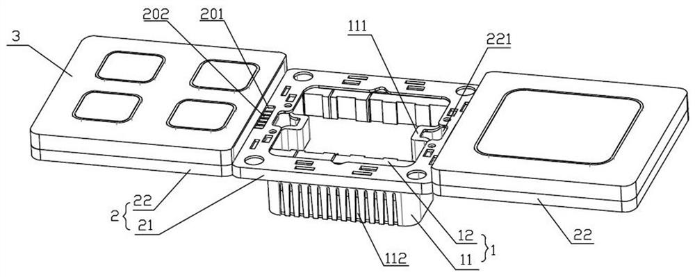
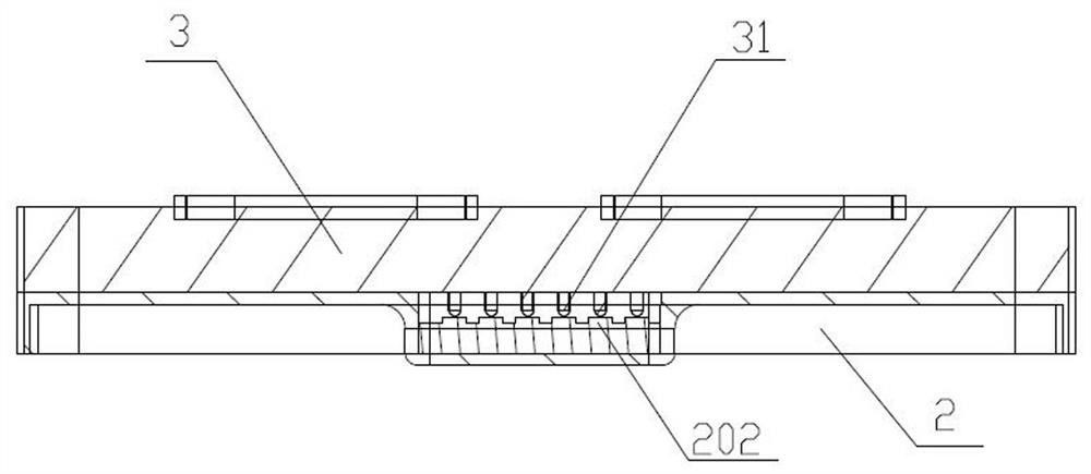
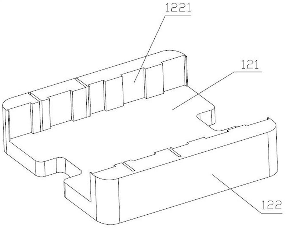
[0026] A multi-switch bottom box connection structure, comprising a cassette 1, a connection panel 2 disposed on the cassette 1, two switch panels 3 disposed on the connection panel 2, and a switch disposed on the switch panel 3; the connection panel 2 It includes a cartridge connecting portion 21 and two switch connecting portions 22 arranged on opposite sides of the cartridge connecting portion 21. The two switch panels 3 are respectively arranged on the two switch connecting portions 22. The control of the two switches The functional modules are all arranged in the cassette 1 . Wherein, the cassette 1 and the connection panel 2 are connected by screws, and the switch panel 3 is directly buckled on the connection panel 2. Of course, the connection panel 2 is provided with an opening above the cassette 1, so as to facilitate the disa...


PUM


Abstract

The invention provides a multi-switch bottom box connecting structure, and belongs to the technical field of switches. The multi-switch bottom box connecting structurecomprises a cassette, a connecting panel arranged on the cassette, a plurality of switch panels arranged on the connecting panel, and switches arranged on the switch panels, wherein the connecting panel comprises a cassette connecting part and a plurality of switch connecting parts arranged on the side of the cassette connecting part, the plurality of switch panels are respectively arranged on the plurality of switch connecting parts, and the control function modules of the plurality of switches are all arranged in the cassette. The multi-switch bottom box connecting structure is simple in structure and convenient to install, and can effectively save manpower and material resources for installing a plurality of switch boxes.

Description

technical field [0001] The invention relates to the technical field of switches, in particular to a multi-switch bottom box connection structure. Background technique [0002] The traditional power switch is basically a structure with a cassette and a panel. If multiple switch panels are to be installed, a corresponding number of cassettes are required, and a corresponding number of grooves are opened on the wall, which is time-consuming and laborious, and requires more materials. In the prior art, for example, the utility model patent with the patent number ZL201220471773.4 discloses a multi-connection switch box, which includes a rectangular switch box body, a pair of female buckles are respectively arranged on a group of adjacent side walls of the switch box, and another A pair of sub-buttons corresponding to the female buckle are respectively provided on a group of adjacent side walls. The female buckle is provided with a card slot, and the sub-button is provided with a ...

Claims


Application Information

Patent Timeline
Patent Type & Authority Applications(China)
IPC IPC(8): H01H9/02H01H1/58H01H1/50
CPCH01H9/0271H01H9/02H01H1/58H01H1/50
Inventor 丁欣欣丁泽成王文广钟诚沈家明王俊锋李建斌
Owner ZHEJIANG YASHA DECORATION
Learn More