Square wave rotor based on outer rotor iron core eccentric structure design
A technology of eccentric structure and external rotor, applied in the direction of magnetic circuit shape/style/structure, magnetic circuit rotating parts, electromechanical devices, etc., can solve the problems of magnetic flux leakage between poles, large differences, large differences in motor or generator performance, etc. , to achieve the effect of improving the air gap magnetic density waveform, reducing the radius and improving performance
- Summary
- Abstract
- Description
- Claims
- Application Information
AI Technical Summary
Problems solved by technology
Method used
Image
Examples
Embodiment 1
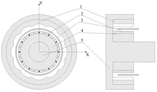
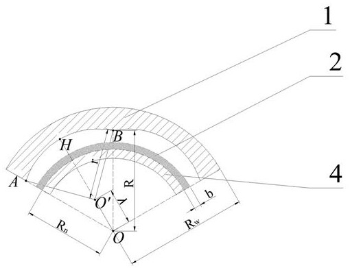
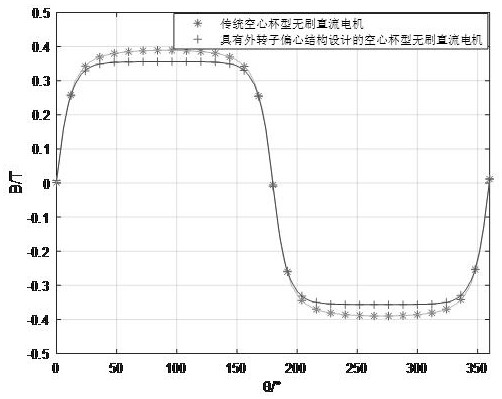
[0030] Embodiment 1 discloses a square-wave rotor designed based on the eccentric structure of the outer rotor core, which is used in a flywheel brushless DC generator. Reference attached figure 1 And attached figure 2 , the entire rotor body includes an outer rotor core 1 , a permanent magnet 2 , a stator without a laminated core 3 , an inner rotor core 4 and a rotor shaft 5 . Both the outer rotor core 1 and the inner rotor core 4 are fixedly connected to the rotor shaft 5 so that the outer rotor core 1 and the inner rotor core 4 rotate together with the rotor shaft 5 . In specific setting, the radially outer side of the outer rotor core 1 is installed on the outer end of the rotor shaft 5 , and the radial inner side of the inner rotor core 4 is installed on the inner end of the rotor shaft 5 . The radially outer side of the inner rotor core 4 is a permanent magnet 2, and the shape of the permanent magnet 2 is tile-like, and its thickness It is determined according to th...
Embodiment 2
[0046] Embodiment 2 discloses a square-wave rotor designed based on the eccentric structure of the outer rotor core, which is used in a hollow-cup square-wave flywheel motor. Refer to the attached Figure 4 And attached Figure 5 , the entire rotor main body components include outer rotor core 1, permanent magnet 2, magnetic isolation block 6, hollow cup stator 3, inner rotor core 4 and rotor shaft 5. Both the outer rotor core 1 and the inner rotor core 4 are fixedly connected to the rotor shaft 5 , so that the outer rotor core 1 and the inner rotor core 4 can rotate together with the rotor shaft 5 . In the specific setting, the radially outer side of the outer rotor core 1 is installed on the outer end of the rotor shaft 5, the radially inner side of the inner rotor core 4 is installed on the inner end of the rotor shaft 5, and the radially outer side of the inner rotor core 4 is permanent. The shape of the magnet 2 and the permanent magnet 2 is tile-like, its thickness is d...
PUM
 Abstract
Description
Claims
Application Information
 - R&D
- Intellectual Property
- Life Sciences
- Materials
- Tech Scout
- Unparalleled Data Quality
- Higher Quality Content
- 60% Fewer Hallucinations
Browse by: Latest US Patents, China's latest patents, Technical Efficacy Thesaurus, Application Domain, Technology Topic, Popular Technical Reports.
© 2025 PatSnap. All rights reserved.Legal|Privacy policy|Modern Slavery Act Transparency Statement|Sitemap|About US| Contact US: help@patsnap.com


